There are various circuits or methods available for building Switched Mode Power Supply (SMPS). SMPS is used for generating controlled and isolated DC voltage from unregulated DC power source. Forward converter circuit is similar to the fly-back converter circuit but it is more efficient than fly-back converter circuit. Forward converter is mainly used for the application which require higher power output (in range of 100 to 200 watts).
Forward converter is basically a DC-to-DC Buck Converter with integration of transformer. If the transformer have multiple output windings you can even increase or decrease the output voltage. It also provides galvanic isolation for the load.
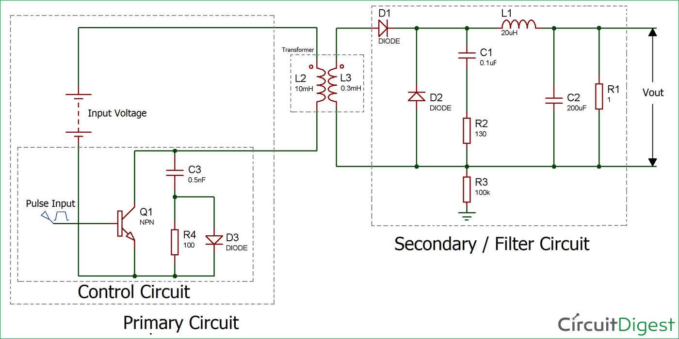
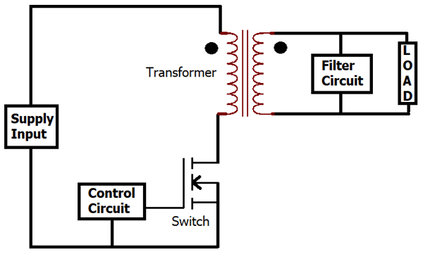
Forward Converter Circuit consists of a control circuit which has a high speed switching device, a transformer whose primary side is connected to the control circuit and secondary side is connected to the filtering circuit. The rectified output from the transformers secondary winding is connected to the load.
As per the above block diagram, when the switch is turned ON, the input is applied to the primary winding of the transformer and a voltage is appeared at the secondary winding of transformer. Therefore, the dot polarity of the windings of transformer is positive, due to this the diode D1 gets forward biased. Then the output voltage of the transformer is fed to the low pass filter circuit which is connected to the load. When switch is turned OFF, the current in the windings of transformer comes down to zero (assuming the transformer to be ideal).
Difference between Forward and Fly-back Converter
| S. No. | Forward Converter | Fly-back Converter |
| 1. | Transformer isolated Buck Converter | Essentially a Buck-Boost Topology |
| 2. | Require one more additional output inductor | Not required |
| 3. | Resetting circuit is needed | Not required |
| 4. | No requirement for output capacitor | Required |
| 5. | More energy efficient | Lower than forward converter |
| 6. | Costlier than flyback converter | Cheaper in comparison with forward converter |
| 7. | Stores energy in inductor when the Transistor turns ON and transfer the stored energy when transistor turned OFF | Transformer of the forward converter doesn’t stores energy |
Circuit Diagram for Forward Converter
Working of Forward Converter Circuit
Mode-I: Powering Mode
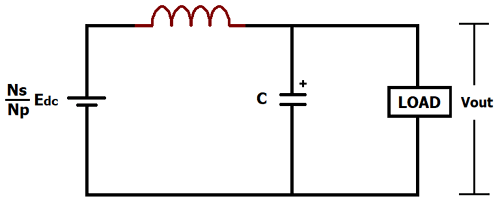
The forward converter said to be in powering mode when the transistor is in ON state. In this condition, the supply voltage is connected to the primary side winding of the transformer and also diode D1 gets forward biased in this condition. Diode D2 will not conduct in this condition, as it will remain reversed biased. Both the windings starts conducting simultaneously when transistor is in ON state. The output at the secondary side of the transformer depends upon the turn ratio (Np / Ns) of the transformer. And, this output voltage is applied to the secondary circuit, which consists of L-C filter. The maximum received output voltage, in case of ideal transformer, at the load will be:
(Ns / Np) * Edc
Where, Edc is the input supply voltage
Np is no. of primary winding
Ns is no. of secondary winding
Mode-II: Freewheeling Mode
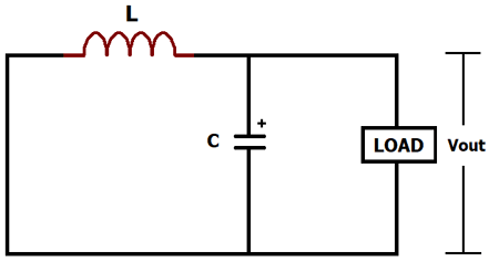
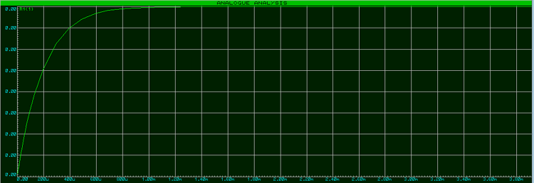
The forward converter said to be in Freewheeling Mode when the transistor is in OFF state. As the transistor turns off, the current of windings of transformer falls to zero (ideally). D1 will be reversed biased in this condition, therefore separates the output section of circuit from the transformer and the input. However, the inductor at the secondary side maintains a continuous flow of current through the freewheeling diode D2. As the input is separated, there is no power flow from the input, but still the load voltage is maintained nearly constant by the charged capacitor and the inductor. Stored energy in the inductor and the capacitor slowly dissipates into the load. Before it dissipates completely the transistor turns ON again to end the freewheeling mode and to maintain the magnitude of load voltage within the required tolerance band. After simulating the above circuit we will get the output waveform as shown below:
Forward converter’s switching frequency is in range of 100 kHz or more.

