Capacitors seem all fine till you get to the point where a power supply fails or refuses to perform optimally. And if the problem is noise, there is a simple fix, you just add more capacitors. But that does not solve it. What could be wrong?
The problem arises from the naïve assumption that capacitors (to a large extent) are ‘ideal’ devices, while in fact, they are not. Those undesired effects are because of something called internal resistance or Equivalent Series Resistance (ESR). Capacitors have a finite internal resistance because of the materials used in their construction. We have explained ESR and ESL in capacitors in details in previous article.
Different types of capacitors have different ESR ranges. For example, electrolytic capacitors in general have higher ESRs than ceramic capacitors. For many applications, it becomes important to measure the internal resistance of capacitors. And today in this article we will build an ESR Meter and learn how to measure the ESR of capacitor using 555 Timer IC and Transistors.
Capacitor ESR Measurement
At the outset ESR Measurement might seem like an easy task.
Resistance can easily be determined by applying a constant current and measuring the voltage drop across the Device under testing.
What if we apply a constant current to a capacitor? The voltage rises linearly and settles at a value determined by the supply voltage, which (for our purposes) is useless.
At this point it is time to go back to something we learnt in school- “Capacitors block DC and pass AC”
After making a few simplifying conclusions, we understand that capacitors are basically a short circuit at high frequencies and the capacitive part is ‘shorted out’ of the circuit and all of the voltage is dropped across the internal resistance.
The advantage of this method is that we don’t even need to know the current if we know the internal resistance of the signal source being used, because now the ESR and internal resistance (of the source) form a voltage divider, the ratio of resistances is the ratio of the voltage drops, and knowing three we can easily determine the other one.
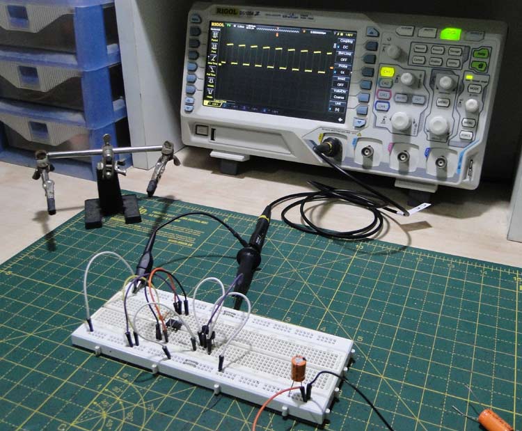
An oscilloscope is used to measure the waveforms at the input and at the capacitor.
Parts List
For the Oscillator:
1. 555 timer – both CMOS and bipolar will work fine, but CMOS is recommended for high frequencies
2. 100K potentiometer – used for frequency tuning
3. 1nF capacitor – timing
4. 10uF ceramic capacitor - decoupling
The Power Stage:
1. BC548 NPN bipolar transistor
2. BC558 PNP bipolar transistor
A quick note about the choice of transistors - any small signal transistor with a high gain (300 and upwards) and a somewhat large current (50mA +) will work fine.
3. 560Ω base resistor
4. 47Ω output resistor – this can be anything from 10Ω to 100Ω.
Circuit Diagram
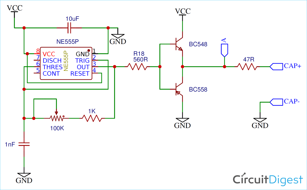
Below is the circuit diagram for this ESR Capacitor Tester circuit-
This ESR Meter Circuit can be divided into two sections, the 555 timer and the output stage.
1. The 555 Oscillator:
The 555 circuit is a conventional astable multivibrator that puts out a square wave with a frequency of a few hundred kilohertz. At this frequency, almost all capacitors act like a short. The 100K pot allows frequency tuning to get the lowest possible voltage across the cap.
2. The Power Stage:
This is a workaround to another problem. We could directly connect the capacitor to the output of the 555 timer, but then we would need to know the output impedance accurately.
To eliminate this, a push-pull output stage with a series resistor is used. The resistor provides the output impedance.
Here is the how the complete hardware of this ESR Meter circuit looks:

Calculating ESR of Capacitor
From the voltage divider equation, we derive the following formula:
ESR = (VCAP • ROUTPUT) / (VOUTPUT – VCAP)
Where ESR is the internal resistance of the capacitor, VCAP is the signal across the capacitor (measured at node CAP+), ROUTPUT is the output resistance of the power stage (here, 47 Ohms) and VOUTPUT is the output signal voltage as measured at point A in the circuit.
While using this circuit it is recommended to set the scope probe to 1X to increase the sensitivity and decrease the bandwidth to get rid of some of the noise in order to make an accurate measurement.
First, the peak to peak voltage is measured at point A, ahead of the impedance and noted. Then the capacitor is attached. Zoom in till you see a square wave. Twiddle the pot till the waveform does not become any smaller.
Depending on the type of capacitor, the peak to peak voltage of the resulting waveform should be in the order of a few tens or hundreds of millivolts.
Example: Measuring ESR for a 100uf Electrolytic Capacitor
Here is the raw output waveform of the power stage:

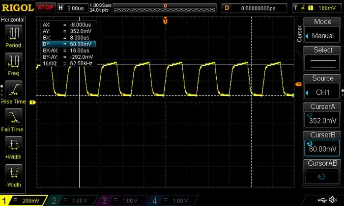
And here is the voltage at the capacitor. Note all the noise superimposed on the signal – be careful with the measurement.

Plugging in the values into the formula, we get an ESR of 198mΩ.
Capacitor’s ESR is an important parameter when designing power circuits and here we have built a simple ESR measuring device based on the 555 timer.


