

Buck-Boost regulator is made using two different topologies, as the name suggests, it consists of both buck and boost topology. We already know that Buck Regulator Topology provides a lower magnitude of output voltage than the input voltage, while a Boost Regulator Topology provides a higher magnitude of output voltage than the provided input voltage. We have already built a 12V to 5V Buck Converter and a 3.7V to 5V Boost converter Circuit using the popular MC34063. But at times, we might need a circuit that can both work as a buck and a boost regulator.
Say, for example, if your device is powered using a lithium battery, then the input voltage range will be between 3.6V to 4.2V. If this device needs two operating voltage 3.3V and 5V. Then you need to design a buck-boost regulator that will regulate the voltage from this lithium battery into 3.3V and 5V. So, in this tutorial, we will learn how to build a simple buck-boost regulator and test it on a breadboard for the ease of building. This regulator is designed to work with a 9V battery and can provide a wide output voltage ranging from 3.3V to 12V with a maximum output current of 4A.
Components Required
- Xl6009
- 10k preset
- 33uH inductor - 2pcs
- 1n4007 - 2pcs
- SR160 - 1pc (for max 800mA output)
- 10uH inductor
- 100uF Capacitor
- 1000uF capacitor -2pcs
- 1uF ceramic or polyester film capacitor
- 9V power source (battery or adapter)
- Breadboard
- Wires for breadboard.
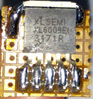
XL6009 Buck-Boost Regulator IC
There are many ways to build a buck-boost circuit, for the sake of this tutorial, we will be using the famous XL6009 DC/DC Converter IC. We have selected this IC because of its ease of availability and beginner-friendly nature. You can also check the article on how to select switching regulator IC to help you with other regulator selection for your switching designs.
The main component is the switching regulator XL6009. The pinout of XL6009 and the specifications are shown in the below image.
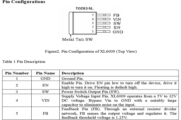
The metal tab is internally connected with the Switching pin of the XL6009 driver ic. The pin description is also given in the above table. The important technical specifications of XL6009 IC is given below
Features
- Wide 5V to 32V Input Voltage Range
- Positive or Negative Output Voltage Programming with a Single Feedback Pin
- Current Mode Control Provides Excellent Transient Response
- 1.25V Reference Adjustable Version
- Fixed 400KHz Switching Frequency
- Maximum 4A Switching Current
- SW PIN Built-in Over Voltage Protection
- Excellent Line and Load Regulation
- EN PIN TTL Shutdown Capability
- Internal Optimize Power MOSFET
- High Efficiency of up to 94%
- Built-in Frequency Compensation
- Built-in Soft-Start Function
- Built-in Thermal Shutdown Function
- Built-in Current Limit Function
- Available in TO263-5L Package
The above specification chart is showing that the minimum input voltage of this driver IC is 5V and the maximum is 32 Volt. Also, as the switching frequency is 400 kHz, it opens up possibilities to use smaller inductors for switching related purposes. Also, the driver IC supports a maximum of 4A output current which is great to cover up many high rated current related applications.
Buck-Boost Converter Circuit using XL6009
The complete buck-boost converter circuit diagram is shown in the image below.

For any switching regulator, the Inductor and the capacitor are the main components. The position of the Inductor and the capacitor in the circuit is very essential to provide the required power to the load during switch on and off condition. In this case, two inductors (l1 and L4) are used that will support buck and boost function individually in this switching circuit. The 33uH inductor that is L1, is the inductor which is responsible for the Buck mode of operation whereas the Inductor L2 is used for the Boost mode inductor. Here I have wound my own inductor using a ferrite core and enameled copper wire. If you are new to making your own inductor, you can check this article on the basics of inductor and Inductor coil design to get started. Once you have built your inductor, you can check its value using an LCD meter or if you don’t have an LCR meter, you can use your oscilloscope to find inductor value using the resonant frequency method.
The input capacitors, C1 and C2 are used to filter transients and ripple from the external battery or the power source. The capacitor C3, 1uF, 100V is used for isolating these two inductors. There is a Schottky diode SR160 which is a one ampere, 60V diode used for converting the switching frequency cycle to a DC and the capacitor 1000uF, 35V is the filter capacitor used for filtering the output from the diode.
As the Feedback threshold voltage is 1.25V, the voltage divider can be set according to this feedback voltage for configuring the actual output. For our circuit, we have used a pot (R1) and a resistor (R2) to provide the feedback voltage.
R1 is a variable resistor which is used for setting the output voltage. The R1 and R2 form a voltage divider that provides feedback to the driver IC XL6009. 10uH inductor L4 and 100uF capacitor C3 are used as an LC filter.
Buck-Boost Converter Construction and Working
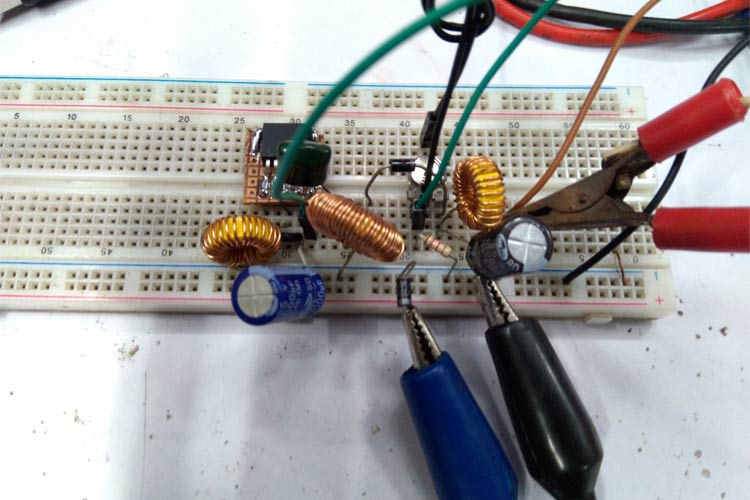
Other than the Inductor, all the components should be available easily. The XL6009 IC is not breadboard friendly. Hence, I have used the dotted board to connect the pins of XL6009 to male header pins as shown below.
Build the inductor as discussed earlier and create your circuit. I have used a breadboard to make things easy but a perf board is recommended. Once complete my circuit on breadboard looked like this.
When the input voltage is higher than the set output voltage, the inductor gets charged up and resists any changes in the current path. When the switch gets off, the inductor provides the charged current via the C3 capacitor and finally rectified and smoothen out by the Schottky diode and capacitor C4 respectively. The driver checks the output voltage by the voltage divider and skips the switching cycle to sync the out voltage as per the feedback circuit output.
The same thing happens during the boost mode when the input voltage is less than the output voltage and the inductor L2 gets charged up and provides the load current during switch off condition.
Testing of XL6009 Buck-Boost Converter Circuit
The circuit is tested in a breadboard. Do note that we have built the circuit on breadboard only for testing purposes and you are not supposed to load your circuit for more than 1.5A when on the breadboard. For higher current applications, soldering your circuit on perf board is highly recommended.
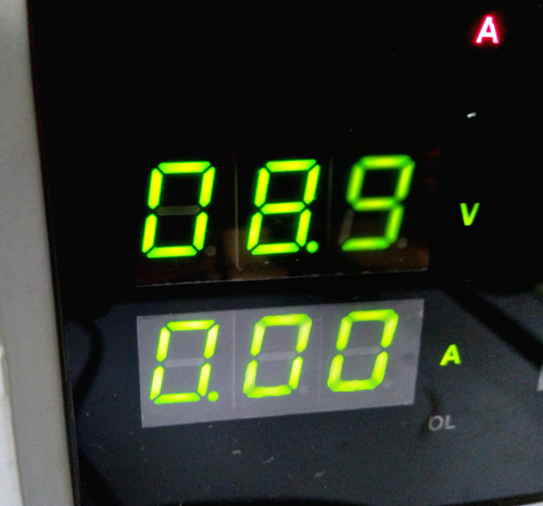
To power the circuit, you can use a 9V battery but I have used my bench power supply which is set at 9V.
The output voltage can be set from 3.3V to 12V using the potentiometer. Technically, the circuit can be designed for a high output current as much as 4A. But, due to the limitation of the output diode, the circuit is not tested in a full load. The output load is set to a decent value of approximately 700-800mA of current. You can change the output diode to increase the output current if required.
To test our power supply circuit, we have used a multimeter to monitor the output voltage and for the load, we have used the DC electronic load something similar to what we build earlier. If you do not have an electronic load, you can use any load of your choice and monitor current using a multimeter. The complete testing video is given at the bottom of this page.
It is also noticed that the output voltage is a bit fluctuating in a +/-5% margin. This is due to the high DCR value of inductors and the unavailability of the heat sink in the XL6009. Adequate heat sink and proper components can be useful for stable output. Overall, the circuit is working quite operational and performance is satisfactory. If you have any questions, leave them in the comment section, you can also use our forums for other technical questions.
Comments
When the internal switch is ON, It flow large current from input and also from Capacitor C3 (discharging) so the chip is working harder than in normal boost mode.

hello,
can you tell me the value of r1 when the output is set to 12v? I want to replace the R1 with a fixed resistor. I've also seen this circuit with an XL-6019 instead of the Xl-6009, can I use the 19 instead of the 09?
best regards