

Sensors are an integral part of any measurement system as they help in converting the real world parameters into electronic signals that could be understood by machines. In an industrial environment, the commonly used type of sensors is the Analog Sensor and Digital sensors. Digital sensors communicates with 0’s and 1’s following protocols like USART, I2C, SPI etc. And Analog sensors could communicate through variable current or variable voltage. Many of us should be familiar with sensors that outputs variable voltage like LDR, MQ gas sensor, Flex sensor etc. These analog voltage sensors are coupled with Voltage to current converters to convert the analog voltage into analog current to become a variable current sensor.
This variable current sensor follows 4-20mA protocol, meaning the sensor will output 4mA when the measured values is 0 and will output 20mA when the measured value is maximum. If the sensor output anything less than 4mA or more than 20mA it can assumed as a fault condition. The sensor outputs the current through twisted pair wires allowing both power and data to flow through only 2 wires. The lowest or ‘zero’ value is 4mA. This is because of the situation in which when the output is zero or 4mA, it can still power the device. Also since the signal is transmitted as current it can be sent to long distance without worrying about voltage drop due to wire resistance or about noise immunity.
In industries, calibration of the sensor is a routine process, and to calibrate the system and also for troubleshooting error results, current loop testing is performed. In current loop testing, it uses a verification process that checks breakage in the communication line. It also checks the transmitter output current. In this project, we will create a basic current loop tester using few components which allows us to manually adjust current from 4ma to 20mA by turning a potentiometer. This circuit can be used as a dummy sensor to emulate programs or for debugging.
Components Requirements
- A PNP Transistor (BC557 is used)
- An Op-Amp (JRC4558 is used)
- 300k resistor
- 1k resistor
- 50k 10 turn potentiometer.
- 100pF 16V
- 0.1uF 16V - 2pcs
- 100R resistor - tolerance 5%
- An LED (Any color)
- 5V power supply
- Breadboard
- Hookup wire
- A multimeter to measure the Current
Let’s take a look at the important components used in this project. In the below image, The PNP transistor, BC557 pin out is shown.

This is one of the most common three pin PNP transistors. BC557 is the identical pair of NPN BC547. From the left to right the pins are Emitter, Base, and Collector. Other equivalent transistors are BC556, BC327, 2N3906 etc.
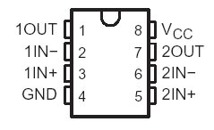
The op-amp used here (JRC4558) follows the same pin diagram as used in other types of the op-amps. The Pin 1, Pin 2, Pin 3 are used for a single op-amp and Pin 5, 6, 7 used for the other channel. Any channel can be used for this project. The 8th pin is the positive supply source and the 4th pin is the GND. The JRC4558D Op-Amp is used for this project, but other op-amps will also work. Such as like - TL072, LM258, LM358, etc.
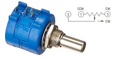
The 5th component in the part list, 50k 10 turn potentiometer is from the Bourns. The part number is 3590S-2-503L. However, it is a bit costly component. The 10 Turn pot is the best for this purpose, but other generic potentiometers also worked just fine. The difference is that the resolution will be less with generic potentiometer because of which the increment or decrement of the current source will not be smooth. In this project, Bourns potentiometer is used. The pinouts of Bourns potentiometer is a bit confusing compared with the standard potentiometer pinouts. In the below image, the first pin from the left is the wiper pin. One needs to be careful while connecting this potentiometer in any application.
Circuit Diagram
The complete Circuit Diagram for the 4-20mA current loop tester is shown below.

As you can see the circuit is pretty simple, it consists of a op-amp which drives a transistor. The output current from the transistor is fed to a LED, this output current can be varied from 0mA to 20mA by varying the potentiometer and can be measured by a Ammeter connected as shown above.
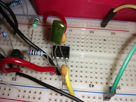
The Op-amp here is designed to work as a current source with negative feedback. The input variable voltage is given to the non-inverting pin of the Op-Amp using a potentiometer. The maximum output current (in this case 20mA) is set by using the resistor connected to the inverting pin of the op-Amp. Now based on the voltage provided to non-inverting pin from the pot, the op-amp will bias the transistor to source a constant current through the LED. This constant current will be maintained irrespective of the load resistance value acting as a current source. This type of Amplifier is called as Transconductance Amplifier. The circuit is simple and can be easily constructed on a breadboard as shown below.
Workings of 4-20mA Current Loop Tester
The LED here acts as the load and the current loop circuit is providing the required current to the load. The load current is supplied by the BC557 which is directly controlled by the op-amp 4558. On the positive input of the amplifier, a reference voltage is being provided by the potentiometer. Depending on the reference voltage, the op-amp provides the bias current to the transistor’s base. The additional series resistor is added across the potentiometer to limit the reference voltage as well as output of the amplifier thus creating the boundary of 0mA to 20mA. Changing this resistor value also change the minimum to maximum current output boundary.
Testing of the circuit
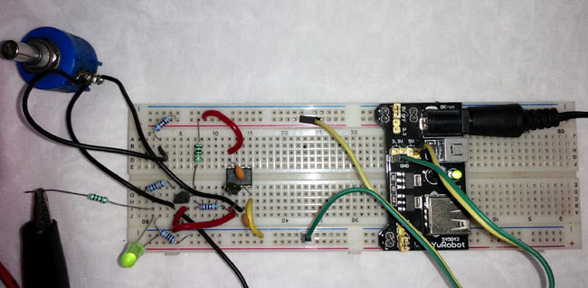
Once the circuit is build, power it using a regulated 5Vsource. I have used the breadboard power supply, similar to what we built earlier to power the circuit as shown below.
Note: For the 300k resistor, two resistors are used in series 100k and 200k.
To test the circuit I have used a multimeter in Amp-mode and connected its probes in place of the ammeter shown in the circuit diagram. You can check this multimeter usage guide if you are new with multimeters. As I vary the potentiometer the current value on the multimeter can be noticed varying from 4mA to 20mA. The complete working video can be found at the bottom of this.
Applications of Current Loop Tester Circuit
The main application of 4-20mA current loop tester is to test or calibrate the PLC machines that receive 4-20 mA protocol and provide data depending on it. Therefore, the wrong calibration resulted in error value perceived by the PLC. Not only calibration, But it is also a convenient process to check the current loop breakage.
The application of the 4-20mA current loop has a huge scope in industrial automation and control system. Such as like, water flow, valve position, Oil production and the associated sensors which are essential for the production process all use 4-20 mA communication line. Debugging and finding fault condition is a crucial job in the industry to save time and money. An accurate 4-20 mA current loop tester is an essential tool to solve the sensor related problems.
Limitations of 4-20mA Current Loop Tester
The circuit has certain limitations. The industrial environment is very harsh than the lab-based environment. Therefore, the circuit should consist of various protection circuits like short circuit protection and surge protections across all input and output which is suitable to use in industrial environments.

The circuit schematic does not match what's on the breadboard. There is an extra capacitor on the board.