

Raspberry Pi is an ARM architecture processor based board designed for electronic engineers and hobbyists. The PI is one of most trusted project development platforms out there now. With higher processor speed and 1 GB RAM, the PI can be used for many high profile projects like Image processing and Internet of Things.
For doing any of high profile projects, one need to understand the basic functions of PI. We will be covering all the basic functionalities of Raspberry Pi in these tutorials. In each tutorial we will discuss one of functions of PI. By the end of this Raspberry Pi Tutorial Series, you will be able to do high profile projects by yourself. Go through below tutorials:
- Getting Started with Raspberry Pi
- Raspberry Pi Configuration
- LED Blinky
- Raspberry Pi Button Interfacing
- Raspberry Pi PWM generation
- Controlling DC Motor using Raspberry Pi
- Stepper Motor Control with Raspberry Pi
- Interfacing Shift Register with Raspberry Pi
- Raspberry Pi ADC Tutorial
In this tutorial we will Control Servo Motor with Raspberry Pi. Before going to servo let’s talk about PWM because the concept of controlling Servo Motor comes from it.
PWM (Pulse Width Modulation):
We have previously talked about PWM many times in: Pulse width Modulation with ATmega32 , PWM with Arduino Uno, PWM with 555 timer IC and PWM with Arduino Due. PWM stands for ‘Pulse Width Modulation’. PWM is a method used for getting variable voltage from a stable power supply. For better understanding PWM consider the circuit below,
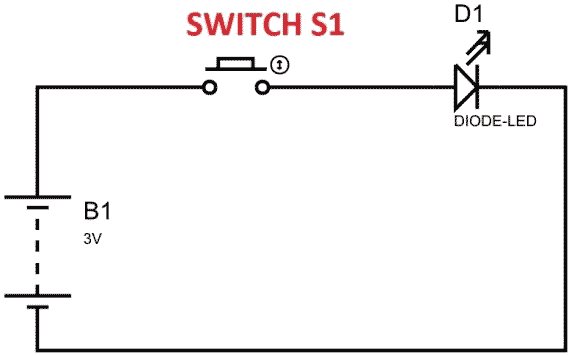
In above figure, if the switch is closed continuously over a period of time, the LED will be ‘ON’ during this time continuously. If the switch is closed for half second and opened for next half second, then LED will be ON only in the first half second. Now the proportion for which the LED is ON over the total time is called the Duty Cycle, and can be calculated as follows:
Duty Cycle =Turn ON time/ (Turn ON time + Turn OFF time)
Duty Cycle = (0.5/ (0.5+0.5)) = 50%
So the average output voltage will be 50% of the battery voltage.
As we increase the ON and OFF speed to a level we will see the LED being dimmed instead of being ON and OFF. This is because our eyes cannot catch frequencies higher than 25Hz clearly. Consider 100ms cycle, LED being OFF for 30msec and ON for 70msec. We will have 70% of stable voltage at the output, so LED will glow continuously with 70% of intensity.
Duty Ratio goes from 0 to 100. ‘0’ means completely OFF and ‘100’ being completely ON. This Duty Ratio is very important for the Servo Motor. The position of Servo Motor is being determined by this Duty Ratio. Check this for PWM demonstration with LED and Raspberry Pi.
Servo Motor and PWM:
A Servo Motor is a combination of DC motor, position control system and gears. Servos have many applications in the modern world and with that, they are available in different shapes and sizes. We will be using SG90 Servo Motor in this tutorial, it is one of the popular and cheapest one. SG90 is a 180 degree servo. So with this servo we can position the axis from 0-180 degrees.
A Servo Motor mainly has three wires, one is for positive voltage, another is for ground and last one is for position setting. The Red wire is connected to power, Brown wire is connected to ground and Yellow wire (or WHITE) is connected to signal.


In servo, we have a control system which takes the PWM signal from Signal pin. It decodes the signal and gets the duty ratio from it. After that, it compares the ratio to the predefined positions values. If there is a difference in the values, it adjusts the position of the servo accordingly. So the axis position of the servo motor is based on the duty ratio of the PWM signal at the Signal pin.
The frequency of PWM (Pulse Width Modulated) signal can vary based on type of servo motor. For SG90 the frequency of PWM signal is 50Hz. To find out the frequency of operation for your servo, check the Datasheet for that particular model. So once the frequency is selected, the other important thing here is the DUTY RATIO of the PWM signal.
The table below shows the Servo Position for that particular Duty Ratio. You can get any angle in between by choosing the value accordingly. So for 45º of servo the Duty Ratio should be ‘5’ or 5%.
POSITION | DUTY RATIO |
0º | 2.5 |
90º | 7.5 |
180º | 12.5 |
Before Interfacing Servo Motor to Raspberry Pi, you can test your servo with the help of this Servo Motor Tester Circuit. Also check our below Servo projects:
- Servo Motor Control using Arduino
- Servo Motor Control with Arduino Due
- Servo Motor Interfacing with 8051 Microcontroller
- Servo Motor Control using MATLAB
- Servo Motor Control by Flex Sensor
- Servo Position Control with Weight (Force Sensor)
Components Required:
Here we are using Raspberry Pi 2 Model B with Raspbian Jessie OS. All the basic Hardware and Software requirements are previously discussed, you can look it up in the Raspberry Pi Introduction, other than that we need:
- Connecting pins
- 1000uF capacitor
- SG90 Servo Motor
- Breadboard
Circuit Diagram:

A1000µF must be connected across the +5V power rail otherwise the PI might shut down randomly while controlling the servo.
Working and Programming Explanation:
Once everything is connected as per the circuit diagram, we can turn ON the PI to write the program in PYHTON.
We will talk about few commands which we are going to use in PYHTON program,
We are going to import GPIO file from library, below function enables us to program GPIO pins of PI. We are also renaming “GPIO” to “IO”, so in the program whenever we want to refer to GPIO pins we will use the word ‘IO’.
import RPi.GPIO as IO
Sometimes, when the GPIO pins, which we are trying to use, might be doing some other functions. In that case, we will receive warnings while executing the program. Below command tells the PI to ignore the warnings and proceed with the program.
IO.setwarnings(False)
We can refer the GPIO pins of PI, either by pin number on board or by their function number. Like ‘PIN 29’ on the board is ‘GPIO5’. So we tell here either we are going to represent the pin here by ‘29’ or ‘5’.
IO.setmode (IO.BCM)
We are setting PIN39 or GPIO19 as output pin. We will get PWM output from this pin.
IO.setup(19,IO.OUT)
After setting the output pin, we need to setup the pin as PWM output pin,
p = IO.PWM(output channel , frequency of PWM signal)
The above command is for setting up the channel and also for setting up the frequency of the Channel”. ‘p’ here is a variable it can be anything. We are using GPIO19 as the PWM “Output channel. “Frequency of PWM signal” we will choose 50, as SG90 working frequency is 50Hz.
Below command is used to start PWM signal generation. ‘DUTYCYCLE’ is for setting the ‘Turn On’ ratio as explained before,
p.start(DUTYCYCLE)
Below command is used as forever loop, with this command the statements inside this loop will be executed continuously.
While 1:
Here the program for Controlling the Servo using Raspberry Pi provides a PWM signal at GPIO19. The Duty Ratio of the PWM signal is changed between three values for three seconds. So for every second the Servo rotates to a position determined by the Duty Ratio. The servo continuously rotates to 0º, 90º and 180º in three seconds.
Complete Project Code
import RPi.GPIO as IO        # calling for header file for GPIO’s of PI
import time                           # calling for time to provide delays in program
IO.setwarnings(False)          # do not show any warnings
IO.setmode (IO.BCM)            # programming the GPIO by BCM pin numbers. (like PIN29 as‘GPIO5’)
IO.setup(19,IO.OUT)             # initialize GPIO19 as an output
p = IO.PWM(19,50)              # GPIO19 as PWM output, with 50Hz frequency
p.start(7.5)                             # generate PWM signal with 7.5% duty cycle
while 1:                                                       # execute loop forever
        p.ChangeDutyCycle(7.5)                   # change duty cycle for getting the servo position to 90º
        time.sleep(1)                                      # sleep for 1 second
        p.ChangeDutyCycle(12.5)                  # change duty cycle for getting the servo position to 180º
        time.sleep(1)                                     # sleep for 1 second
        p.ChangeDutyCycle(2.5)                  # change duty cycle for getting the servo position to 0º
        time.sleep(1)                                     # sleep for 1 second
Comments
Check this Servo Motor Control using Arduino and Servo Motor Tester
Do you have to run the servo off the 5v pin for the code to work or could you run it off an external power source?
This servo (sg90) can be run using power from RPi, but if you use more powerful servo then you need external power source.
can i use PIR MOTION..IF THE THE pir motion detect he can run into 60 or 90 degree if there no motion he can reverse to original position
Yes you can, just interface the PIR sensor with PI and change the code. The following link will help you get started
https://circuitdigest.com/microcontroller-projects/raspberry-pi-motion-…
how to control servo motor using pir motion sensor with raspberry pi 3
what do you mean to change the code sir

I want to control servo by using keys so plz help me