
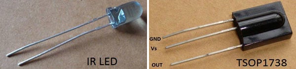
IR LED emits infrared light, and used in TV remotes. This Infrared is received by the receiver TSOP17XX (TSOP 1738used in TV). TSOP17XX receives the modulated Infrared waves and changes its output. TSOP is available in many frequency ranges like TSOP1730, TSOP1738, TSOP1740 etc. Last two digits represent the frequency (in Khz) of modulated IR rays, on which TSOP responds. Like for example TSOP1738 reacts when it receives the IR radiation modulated at 38Khz. TSOP output is active low, means it becomes LOW when IR is detected. Here we will build a Infrared Light Switch with Remote Control which can be operated wirelessly using any IR Remote like TV remote, AC remote etc.
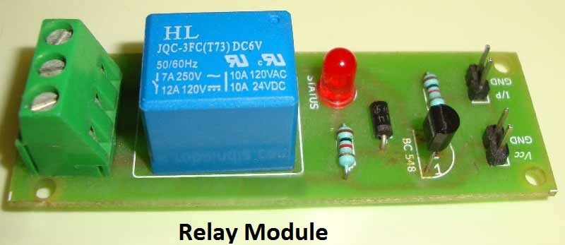
In this remote controlled switch circuit we are using TV remote to ON/OFF the AC light by pressing any button of remote, and using the TSOP1738 at receiver end. Receiver circuit is connected to AC appliance via Relay, so that we can control the light remotely. We have used IC 4017 to convert it into a push ON, push OFF switch. Go through this article to understand the IR Transmitter and Receiver. Here we have used TSOP1738 as IR reciever.
[Also check: TV Remote Control Jammer Circuit]
Normally when we press any button of TV/DVD player remote, Light glows and as soon as we release Button, it becomes OFF. Now it can be converted into a PUSH ON and PUSH OFF toggle switch using IC CD4017. IC CD4017 is a CMOS decade counter IC. It can produce output at the 10 pins sequentially, i.e. it produces output one by one at the 10 output pins. Output is switched to one pin to another by applying a clock pulse at pin 14. Learn more about IC 4017 here.
When firstly, power is applied to IC 4017, output at PIN 3 (Q0) is HIGH, when we press the button of IR remote, then a LOW to HIGH clock pulse is applied to PIN 14 (first clock pulse) and output at Q0 becomes low and PIN 2(Q1) becomes HIGH. PIN 2 triggers the RELAY module, and the AC light becomes ON. Now this position will remain until the next clock pulse. If we press the Button of IR remote again (second clock pulse), output at Q1 becomes LOW and Q2 becomes HIGH. This will deactivate the Relay and switch off the light. And because Q2 is connected to the RESET pin 15 of 4017, it will reset the IC and again output at Q0 becomes HIGH and Q2 becomes LOW (initial state). So it works like a toggle switch.
IR Remote Control Switch Circuit Diagram

In above IR Remote Control Light Switch, Output of TSOP1738 oscillates at the rate of 38KHz, which is applied to clock pulse of 4017. So we have connected a 1uF capacitor across the output of the TSOP so that this 38KHz pulse train is counted as one clock pulse to the IC 4017.
We can also use the IR transmitter circuit to ON/OFF the Bulb, this IR transmitter circuit produces modulated IR at 38KHz like a TV remote. Also we can replace Bulb with any AC appliance, which is to be controlled by remote control.
Comments
Thank u very much.
Thank u very much.
The circuit worked with me well i applied it to 12v dc led back up system but the problem is the circuit disturbed by outer frequencies for example when i turn on a CFL light the circuit start on and of several time before it stabilized again .so ho i could make the sensitivity of the circuit less.
regards
Try to use bandpass filter
Try to use bandpass filter with the Receiver part.
Thank you for your replay...
Thank you for your replay...
Should the bandpass filter connected to the output of TSOP1738 then the rest of the circuit is the same and what range of frequencies you suggest to work with .
Regards
Yes, rest of the circuit will
Yes, rest of the circuit will be same. Band pass filter should work well and TSOP output shouldn't get disturbed by other frequencies other than 38KHz.
Thank you for your kind
Thank you for your kind response,
Using Band pass filter either is hard or not cost effective, the passive band filter is hard to be constructed since its very difficult to find the predetermined values for capacitors for example in L-C circuit while using active filter such LM741 circuits need more space and need 2 IC's to construct the circuit - Those most of circuits i found on the Internet - one of the solution discussed is using LM567 IC with the CD 4017 so the circuit of IR remote switch will need little modification.
I will be very grateful if you kindly give me your opinion and if possible i need your help to re-modify the schematic withe LM567 solution if its appropriate.
Thnk u very much.
Regards
Hi Madox, If you look at the
Hi Madox, If you look at the datasheet of TSOP17XX, it have all the circuitry to avoid the disturbance, like Bandpass filter, AGC etc. This circuit is working fine for me, you can also use a RC circuit at the clock PIN of 4017 to avoid the unexpected results, generated while pressing remote button. RC circuit at clock pin has been also used in this Circuit.
Hi Maddy, can you send me the
Hi Maddy, can you send me the Simulation of this circuit ???
Can i use 2138 sensor?
Can i use 2138 sensor? Because it could not work. Please help on this issue.
Thank you.
yes, you should use another
yes, you should use another 555 timer in monostable mode, in place of 4017 IC. Remove the BC557 transistor and connect the Trigger PIN to the 10k resistor at the OUT pin of TSOP.
Hi Jayant can you send me the
Hi Jayant can you send me the Software Simulation of the above circuit ???
my circuit is not working....
is the transistor bc557 is connected in right position or it is in revers bias
Question on the circuit of Remote Controlled Switch
Can you please specify what is the min-max operating distance range for this circuit?
In case i need to place the receiver circuit on the wall, can I be able to operate from a distance of 10 feet etc?
Thanks,
--sameer
I test the circuit and it
I test the circuit and it worked on 8M which is about 26 feet , and i think it will work on more distance .
the distance the receiver can operate with is based on the signal strength of your transmitter device.
regards
sir i hv made the circuit
sir i hv made the circuit till the led on pin 2 but i have not connected the relay,,,but the led is not stable,,it is on for the moment i press the switch and it goes off when i release the switch...what could be the problem?????
Try using RC circuit at the
Try using RC circuit at the clock pin of the IC4017, as described in this article Toggle Switch (last paragraph)
Not working
Sir .i had connected rc ckr (o.1microf capacitor &220k resistor )but it still not working and red light continue blinking on off unexpectively ..please sir give me any solution
1 microfarad capacitor's voltage?
Hi Sir,
Could you please tell me what is the voltage of the 1 microfarad capacitor? Will there be no reverse voltage from the capacitor? That is, the capacitor's positive voltage cannot travel to the output pin of the TSOP receiver?
Thanks!
Multiple buttons
Hello,
Thank you for this clear and easy explanation, I have a question. Is there anyway to translate signals come from many buttons in the remote control to switch multiple outputs ?
Yes, IR remote sends a
Yes, IR remote sends a particular hex/decimal code on each button press, so by this we can identify the pressed button and use that button to operate a particular device. We have explained it here: IR Remote Controlled Home Automation using Arduino
Good say's!
Very well written!
I will right away seize your rss feed as I can not to find your
email subscription link or newsletter service.
Do you have any? Kindly allow me recognize in order that I may subscribe.
Thanks natamolestr!
Thanks natamolestr!
Subscription box is given at the bottom of every page, just enter your Email address and hit Subscribe button.
Thank's, very interesting article
Well written!
I’ll right away grab your rss as I can not find your
e-mail subscription link or e-newsletter service.
Do you’ve any? Please allow me understand in order that I may subscribe.
Hi
Hi
Some suggestions needed... I have to make it cost effective hence the 2 things i am looking to forego
1. The 9v Battery - What possible other could be to forego the battery how can i give it a alternate source?
2. IC 4017 - can i use something else other than the IC 4017, the main reason to not use is the Space it uses! Can i use a 555 instead ?
Looking forward to hear from you !
Cheers...
Try using 3v Button cells.
Try using 3v Button cells.
You can use 555 as a Switch instead of 4017.
Thanks for this circuit. It
Thanks for this circuit. It was working but there is a little problem. After a few seconds after it is ON. It will automatically OFF and the bigger the load the quicker it turn off. . . What should I do? Thanks
Switching ON time is not
Switching ON time is not related to the AC load in any way, whether you connect TV or a Zero wall bulb. Check that your components are not faulty, also check your connections again.
which remote works?
i tried using all the tv and ac remotes that i had but still not working
which remote works the best?
Any TV or DVD remote will
Any TV or DVD remote will work, I think problem is in your circuit. Please check your circuit again and try to debug it. Or try to use IR LED as a transmitter like here :IR Transmitter and Receiver
ckt not working
Hey, description is really appreciable and I tried this but its not working . Maybe the remote is not working . Can I make transmitter for the above ckt if I do not use tv remote
Yes you can make transmitter
Yes you can make transmitter using IR LED like here: IR Transmitter and Receiver or if you want to assign different functions to the buttons of IR remote then use Microcontroller like here: IR Remote Controlled Home Automation using Arduino
CONTROL 10 DEVICES WITH PIC IC USING TSOP THROUGH TV REMOTE
sir
i will connect the tsop ic with any pin of PIC ic and connect the relays to 10 any other pin....now i am not able to understand how it work ... what happend if we press 1 or 2....
if possible ...can you send me code for the same at my email id or post here too
thnx
If you want to assign
If you want to assign particular function to the particular button then you need to first decode your IR Remote to Hex code. Check this project: IR Remote Controlled Home Automation using Arduino
am designing project but once
am designing project but once am applying power the lamp turns oN directly help please
You have probably reversed
You have probably reversed the connection for NO and NC in Relay, means you have connected NC in place of NO and vice versa.
thank you very much.thank you very much
thanks sir very very thanks
the cathode end of the diode
the cathode end of the diode is given +9v supply, that means the diode is reverse biased??
can anybody explain me this part?
can anybody tell me the sequence of the circuit.??
Every Inductor coil produces
Every Inductor coil produces equal and opposite EMF when switched OFF suddenly, this may cause permanent damage to components, so Diode must be used to prevent reverse current.
Hi,the TSOP1738 output goes
Hi,the TSOP1738 output goes to the base of the pnp transistor,but why the collector is wired to the positive rail,it should be an npn transistor.
Because TSOP output is active
Because TSOP output is active low, further check this to understand TSOP and purpose of PNP transistor: IR Transmitter and Receiver
Bulb not glows
My relay module is working perfecly, its light glows and off when I press the remote button
But bulb which is connected to the NO and COM pin of the module does not glows
I changed several buttons but not get the result
Kindly assost me
Remote Controlled Light Switch
The transistor should be of pnp type as the emitter is connected to negative
Which capacitor used?
Which capacitor used in this circuit and how many volt...
1uF, 50v you can use any
1uF, 50v you can use any normal 1uF capacitor.
Please mail me circuit how to
Please mail me circuit how to control fan and light seperately using same IR receiver
a doubt in the remote controled switch circuit
Sir i dont understan the 4th pin of the ic 4017 goes to 15 MR where is the 15th pin and what is MR?please explain me sir iam new to this field thank u sir.
Check this circuit to learn
Check this circuit to learn more about IC 4017: Toggle Switch
can i use tsop1838 insted of
can i use tsop1838 insted of 1738...if i use 1838 then any changes required for the circuit???please help my project is not working
unstable output for tsop 1738
I'm facing unstable output of tsop 1738.
It is not stable. What should i do.
not working
i made above circuit but not working.......used hs0038 instead of tsop1738.......anybody help me?
How to control two numbers of electrical devices.
I want to control two numbers of electrical devices. Please tell me the procedure as soon as possible.
You can connect both the
You can connect both the devices in parallel to this circuit. Both will turn on on first button-click and then turn-off on second click.
Jayant - pls let me know what
Jayant - pls let me know what is the output voltage/amperage of this whole circuit. I am asking to know if we can control any AC/DC device (9V DC or 240V AC) and current ranging from 1A to 16A ??
Yes we can control any device
Yes we can control any device, just we need to choose Relay of proper rating.
IR Lighting Controller Using Arduino
Hi to Everyone, can somebody help me with the explanation about how can I use IR Remote to control lights?
pls I can't get the TSOP1738
pls I can't get the TSOP1738 all I can see is TFM5300 and I can't simulate it to work, need help its very urgent thanks
Can we connect more than 1
Can we connect more than 1 bulb ? If yes then how?
If you want to switch on all
If you want to switch on all the devices from one button then us multiple Relay module with this circuit, otherwise if you want different buttons for different appliances then use microcontroller like here: IR Remote Controlled Home Automation using Arduino
it better to use 5v supply
when i used 9v supply it didnt work and tsop seems to be damaged but when i used 5v every thing is ok
more stability for tsop sensor
i would like to share some info :
tsop is very sensitive sensor for any supply ripple so try to use very very stable power supply
another important info according to tsop datasheet you have to add resistance to tsop vss pin berfore connecting it to supply this helped me to stabilize tsop sensor very much in datasheet they recommend 100 ohm but i put 500 ohm and tsop stability improved very much
try to provide tsop circuit with independent supply the noise or ripple happen due to relay switch and load voltage drop can effect tsop supply causing unwanted output
try also to put tsop in box and cover its input by semitransparent sheet like tissue paper to reduce any interference for light sources although its mentioned that tsop manufacturer got this point covered
good luck
Does the circuit works on 230 v 50 hz supply
As we to built a project based on this so we r trying to make it using 230v 50 hz supply so shall we use a rectifier/filter and transformer before this circuit to make it work on 230 v 50 hz supply...???
Ans fast as it is an urgent need..??
Hello im from iran thank you
Hello im from iran thank you ican that to make a remote control .thank you very much .in our sites not find things
You can use 6v relay avilable
You can use 6v relay avilable in markeets
Can i use triac instead of
Can i use triac instead of relay, the what shud be ckt, pl responce
what is the function of BC547
what is the function of BC547, CAN I USE TRIAC IN pin2, PLEASE THEN CKT DIA
I want to use both mechanicalswitch as well as by remote
I want to use both mechanical switch and remote switch(by remote) together, can you suggest me circuit for that ?
remote controlled light switch
i am just a beginner. can anybody suggest me a stimulation software...
ISIS proteus is a good choice
ISIS proteus is a good choice for beginners
The Tsop 1738 output is
The Tsop 1738 output is unstable its keeps coming on and off by itself
Sounds odd... Is your circuit
Sounds odd... Is your circuit correct?
If yes, try changing the TSOP, yours might be a faulty one.
remote controle light switch
thank you for your circuit it work but I find a small problem reciver infrared and IC 4017 it work with a power supply 5V but relay it works with a power supply 8v
what supply used?
9V battery is used for
9V battery is used for powering the project, the 4017 IC can also work on 9V
RC circuits
very useful circuit, please anybody send me simple to hard all circuits diagrams control with radio or other signals, for drone circuit bord , control to 4 motors. please help me
remote control on off switch
Hi!
I am having a problem with the circuit. It stays switched ON for couple of seconds and switches OFF by its self. I have covered all the points discussed but still the problem exists. Can any one give me a tip to over come this problem and also to make a robust circuit which works without any hitch.
Regards
Can someone please list out
Can someone please list out all the components required with corresponding specifications other than asking me to look for them in the circuit

Thanks very much for your simple description,it was usefully for me very much