In this tutorial we are going to build a Heart shaped serial LED flasher circuit using 555 timer IC and 4017 IC. It is an interesting DIY which you can build for yourself or gift someone special to you.
Required Components
555 Timer IC
Decade Counter IC 4017
Resistors - 220 Ohm, 1k and 10k
Capacitor - 10µF
LEDs - 8
battery - 9v
Breadboard and connecting wires
Circuit Diagram and Explanation
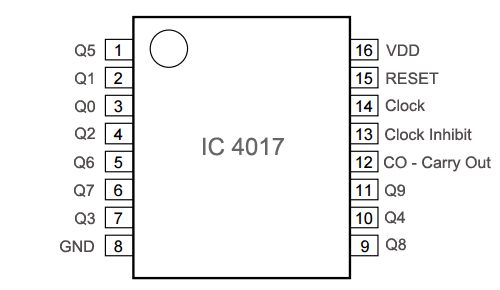
Before we look into the circuit details, we need to understand about 4017 IC, which is a CMOS decade counter IC. It can produce output at the 10 pins sequentially, i.e. it produce output one by one at the 10 output pins. This output is produced through the clock pulse at PIN 14. First clock pulse makes first output PIN (PIN 3) HIGH, second clock pulse makes first PIN LOW and second PIN (PIN 2) HIGH, third clock pulse makes third PIN HIGH, and so on. So it creates sequential ON and OFF of all the 10 OUTPUT PINs which is needed in our serial LED flasher circuit. Below is the PIN diagram and PIN description of 4017.
IC 4017 Pin Diagram

IC 4017 Pin Description
PIN NO. | PIN Name | PIN Description |
1 | Q5 | Output 5: Goes high in 5 clock pulse |
2 | Q1 | Output 1: Goes high in 1 clock pulse |
3 | Q0 | Output 0: Goes high at the beginning – 0 clock pulse |
4 | Q2 | Output 2: Goes high in 2 clock pulse |
5 | Q6 | Output 6: Goes high in 6 clock pulse |
6 | Q7 | Output 7: Goes high in 7clock pulse |
7 | Q3 | Output 3: Goes high in 3 clock pulse |
8 | GND | Ground PIN |
9 | Q8 | Output 8: Goes high in 8 clock pulse |
10 | Q4 | Output 4: Goes high in 4 clock pulse |
11 | Q9 | Output 9: Goes high in 9 clock pulse |
12 | CO –Carry out | Used to cascade another 4017 IC to makes it count upto 20, it is divide by 10 output PIN |
13 | CLOCK inhibit | Clock enable pin, should kept LOW, keeping HIGH will freeze the output. |
14 | CLOCK | Clock input, for sequentially HIGH the output pins from PIN 3 TO PIN 11 |
15 | RESET | Active high pin, should be LOW for normal operation, setting HIGH will reset the IC (only Pin 3 remain HIGH) |
16 | VDD | Power supply PIN (5-12v) |
Now we can connect 10 LEDs (or less than ten), to the 10 output pins of the IC in a heart shape in a sequence. All we just need to apply clock pulse to the PIN 14, and that clock pulse is generated by 555 timer IC in Astable mode. We can control the speed the of flashing LEDs by changing the value of Resistors (R1 and RV1) and/or Capacitor (C1) of 555 timer IC, because changing the resistors or capacitor will change the oscillation frequency of 555 timer, hence the rate of clock pulse. We have used variable resistor RV1 so that we can change the clock pulse rate on the board itself. You can also check here a simple LED Flasher using 555 IC.


How to use the remote control in room fan