A decimal counter is a chip designed to count the number of pulses or events that occur in digital circuits. These chips show the output in the decimal form or 1 to 99... form. So if we have a 12 bit counter, then it can count only 12 clock pulses or 12 events. These chips memorize the events and show the count of events at output port. The chip memorizes the event and shows the output in decimal form, hence the name DECADE COUNTER. what decade counter does it each time a pulse is appeared at clock pin, it counts it and stores the value. We will discuss more about that in the working part.
Here we are going to use a 10 bit DECADE counter. The counter chip is CD4017BE.With a 10 bit DECADE counter; we can count events up to 10. So it would take 11 clock pulses for the chip to reset itself to zero.
These counters have limitations for working voltage and clock frequency. When these limitations are not considered the chip may damage permanently, so one should pay attention while selecting the canary counter.
Components Required
Power supply (5v)
1K, 220Ω resistors
CD4017 DECADE counter IC
10 LEDS
Connecting wires and breadboard.
Circuit Diagram and Working Explanation
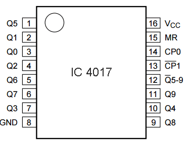
The IC 4017 pin configuration is show in figure.

Here the pin no. 13 “CLOCK ENABLE” should be grounded for the chip to count the events or clock pulses, the pin no 12 “CARRY OUT” is for next counter chip, this pin is connected to next chip clock pin if we were to increase the counter capacity. It can be ignored if the 10 bit count is enough.
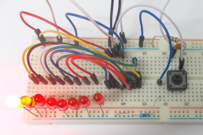
The circuit starts at clock pin, here we pull down the clock pin to ground through a 1KΩ resistor. This is to be done because the binary counter is a rising edge type. So whenever a positive rising edge is generated at clock pin the counter recognizes it as an event and increments the binary output by one.
Now the clock is provided with a button, so for every button press there will be a positive peak at the clock pin and hence an event. The DECADE counter has a capability to drive the LED directly so there is no need for resistors at the end of binary counters LEDS. The MR (Master Reset) of binary counter must be pulled down at any time, leaving it open might cause unpredictable results at the LEDS might blink randomly.
The capacitor is for neutralizing the bouncing effect of the button. In the absence of capacitor, the counter may count the events occurring wrongly.
The connections which are done for CD4017 are given below:
PIN16 to +5v supply
PIN8, PIN15, PIN13 to Ground
PIN14 to Button
PIN1 to Ground through 1k resistor
PINS 3,2,4,7,10,1,5,6,9,11 Connected to LEDs
So every time a peak is passed the counter considers it as an event and increments the output by one for every passing event, once it reaches it limit to track the events it automatically resets to zero and starts again to count the pulses. And for the output it provides the event number as binary output through pins 3,2,4,7,10,1,5,6,9,11,12. In LSB (Least Significant Bit) to MSB(Most Significant Bit) fashion. so if the event count is seven the pin “6”will be high and so the corresponding LEDs glow. To reset the counter to zero under any stage connect the MR pin of counter to +5V, this resets the counter to zero. Also check these circuits based on decade counter IC 4017:
Comments
Decimal counter circuit using 4017
Is a 4017 capable of remembering groups of numbers? Can it, for example, be configured to recognize a predetermined number? I am thinking of the number four.. I want a circuit that will count the number of 'push button' pulses and then add whatever it takes to total four. (1+3, 2+2, 3+1) I am trying to design a game using 21 LED's in which a player pushes a button to light 1, 2. or 3 LED's. Then a 'machine' button is pushed and the circuit itself lights a number of LED's that totals four.
This 4017 tutorial is very informative and I will be experimenting with it.
Decimal Counter Circuit
The commentary says that Pins 9, 11 and 12 are connected to LED's. The schematic shows those pins not connected to anything. Which is right? Also,
the schematic shows voltage is applied to the 4017 via pins 13, 14 and 15 while the commentary says it is applied to Pin 16. Is it possible that I have a different
4017? (Do all 4017's have the same pin configuration?) Lastly, the supply voltage is shown as 5V. How critical is that voltage? Is there a range of voltages that will still work the circuit?
You can connect two more LEDs
You can connect two more LEDs at 9 and 11, as 4017 is ten stage decade counter. Pin 12 (CO) is for multiplexing the other 4017 chip to count more than 10.
Pin 13 and 15 are grounded and Pin 14 is for Clock input. Voltage has been given at PIN 16 (not shown in the circuit), see the text in Circuit Diagram. Circuit diagram is correct.
"Circuit diagram is correct."
"Circuit diagram is correct."
The diagram might be but the notes aren't. Typo/
"PIN1 to Ground through 1k resistor"
That's not shown in the schematic. Pin1 is decoded output "5".
Pin14 is connected to ground through a 1K resistor.


GREAT, been looking for this for weeks.