
Electronic clock with LED pendulum & tick tock sound produces Tick Tock sound every second and it has a LED pendulum in which 6 LED glow in forward and reverse sequence like a Pendulum, each LED glow in one second. This circuit is very useful and inexpensive. You can build your own clock which can be used in many applications like toys, robots etc. To create this circuit we have mainly used 555 timer IC, 4017 IC and a speaker. We have used 555 IC to produce the clock pulse every second and 4017 as a decade counter to glow the LEDs in sequence.
4017 IC
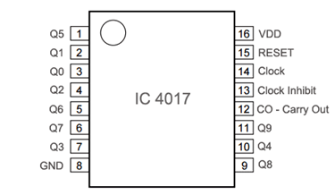
4017 IC is a CMOS decade counter chip. It can produce output at the 10 pins (Q0 – Q9) sequentially, means it produce output one by one at the 10 output pins. This output is controlled through the clock pulse at PIN 14. At first, output at Q0 (PIN 3) is HIGH, then with each clock pulse, output advance to the next PIN. Like one clock pulse makes the Q0 LOW and Q1 HIGH, and then the next clock pulse makes the Q1 LOW and Q2 HIGH, and so on. After the Q9, it will start from the Q0 again. So it creates sequential ON and OFF of all the 10 OUTPUT PINs. Below is the PIN diagram and PIN description of 4017:
|
PIN NO. |
PIN Name |
PIN Description |
|
1 |
Q5 |
Output 5: Goes high in 5 clock pulse |
|
2 |
Q1 |
Output 1: Goes high in 1 clock pulse |
|
3 |
Q0 |
Output 0: Goes high at the beginning – 0 clock pulse |
|
4 |
Q2 |
Output 2: Goes high in 2 clock pulse |
|
5 |
Q6 |
Output 6: Goes high in 6 clock pulse |
|
6 |
Q7 |
Output 7: Goes high in 7clock pulse |
|
7 |
Q3 |
Output 3: Goes high in 3 clock pulse |
|
8 |
GND |
Ground PIN |
|
9 |
Q8 |
Output 8: Goes high in 8 clock pulse |
|
10 |
Q4 |
Output 4: Goes high in 4 clock pulse |
|
11 |
Q9 |
Output 9: Goes high in 9 clock pulse |
|
12 |
CO –Carry out |
Used to cascade another 4017 IC to makes it count upto 20, it is divide by 10 output PIN |
|
13 |
CLOCK inhibit |
Clock enable pin, should kept LOW, keeping HIGH will freeze the output. |
|
14 |
CLOCK |
Clock input, for sequentially HIGH the output pins from PIN 3 TO PIN 11 |
|
15 |
RESET |
Active high pin, should be LOW for normal operation, setting HIGH will reset the IC (only Pin 3 remain HIGH) |
|
16 |
VDD |
Power supply PIN (5-12v) |
Components
- CD4017 IC
- 555 Timer IC
- 2 Resistor- 1k
- Capacitors- 10uF, 100uF
- Variable Resistor- 100K set at 72k
- Diodes- 8 (1n4148 preferred)
- 6 LEDs
- Speaker 8ohm
- Power supply 5-9v
Circuit Explanation
Circuit can be divided into 3 parts:
(a) LED glowing in pendulum sequence
(b) 555 Timer IC as a timing device
(c) Tick tock sound generator

(a) LED glowing in pendulum sequence:
We have connected 6 LEDs to the output Q0 to Q5, now after 6 LEDs we need to glow them in reverse order. To achieve this, we have connected middle 4 LEDs to the output Q6-Q9 too. Means middle 4 LEDs are connected to the two outputs i. e. Q1-Q4 and Q6-Q9. Diodes have been used to connect middle 4 LEDs, to prevent the reverse current flow, so that when one output is HIGH, current can’t be gone through another connected output. So now finally, LED 1 to 6 glows, then LED 5 to 2 glows (reverse) and then again LED 1 to 6 glows, then 5-2 again and so on. Each LED glow indicates a second, because 555 has been set to produce a clock pulse per second.
(b) 555 Timer IC as a timing device:
555 timer is very good component to calculate the time, from milliseconds to hours. To apply the clock pulse at PIN 14 every second, we have used 555 timer IC in Astable mode. The oscillated output generated at PIN 3 of 555 has been applied to the PIN 14 of IC 4017, so that 4017’s output can be advanced with each clock pulse. Here the value of R1 (1k), R2 (72k) and C1(10uF) has been chosen is such manner so that the 555 oscillate with a Time period of approx. 1 second and duty cycle of approx. 50%. The Time period of the 555 can be calculated using this formula: T=0.693*((R1+2*R2)*C1)
(c) Tick tock sound generator:
Finally we have connected a Speaker with a 100uF capacitor to the output (PIN 3) of 555 Timer IC, so that a tick tock sound can be generated with each clock pulse means per second. Also check this ticking sound circuit
Use proper power supply for the circuit, a weak battery can give unexpected result. Computer’s USB 5v supply can also be used for testing.
Comments
Something missing in the schematic
In the schematic you forgot to give power to the 4017 (pin 16)

hi good day i wonder if you can give the step by step procedure ..the way you put every materials on the breadboard im going to make this as a final project for my electronics subject thank you so much