

People may access messages, alerts, health information, and other advanced information easily and quickly using smartwatches. While smartwatches are formally revolutionary as standalone devices, their capabilities essentially increase when used in conjunction with other devices that people carry, such as their smartphones or tablets. In this project, we are going to build a feature-rich, customizable smartwatch from scratch. We are going to make this using the best affordable and easily available components. Since designing such a product is a lengthy time-consuming procedure, we are going to do this in parts.
In this first part of the series, we are going to look at the basic structure of the project. We will decide the basic feature we need, and the core components we are going to use.
DIY Smartwatch Functional Block Diagram
The image below represents the basic block diagram of the smartwatch we are going to make.
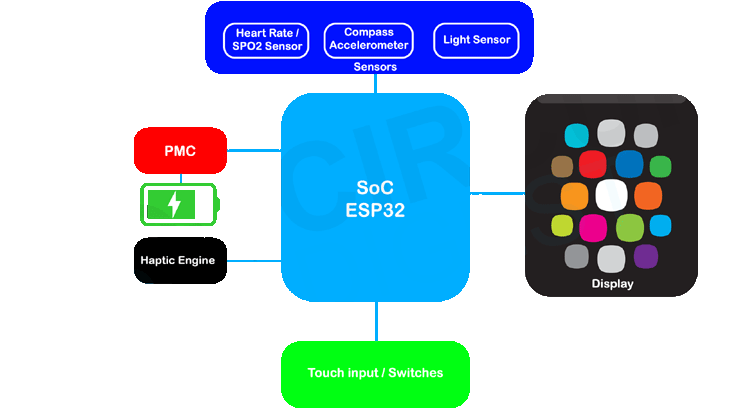
The smartwatch consists of the following basic block. We will discuss the functions of each block and the exact components used will be determined in the following parts.
SoC: As we know in an embedded system the brain will be a microcontroller or a microprocessor. For the smartwatch project, we have selected the ESP32 as the SOC (System on Chip), since it is cheap, feature-rich, and can be easily programmed with a friendly IDE like Arduino IDE. This will enable the community to develop or modify the smartwatch with ease.
Display: As we know the display is also a very important part of the project. There are multiple types of displays available in the market. I have considered two displays for the project. 1.28” round TFT display with GC9A01 controller and 1.69” rounded corner rectangular display with ST7789V controller. Both are excellent IPS Panel displays with a resolution of 240x240 pixels (GC9A01) and 240x280 (ST7789V). I chose the bigger display with a higher resolution.
Power Management Circuit (PMC): The PMC will contain all the power-related circuits, including the battery charger and the buck-boost converter.
Haptic Engine: The haptic engine will consist of a haptic feedback device such as a vibration motor or a linear vibration motor. We will use it to provide the necessary haptic feedback to the user during the necessary event such as call or message notifications or health notifications.
Sensors: The basic sensors we are planning to incorporate with the project are the heart rate/ SPO2 sensor, compass sensor, and ambient light sensor.
Touch inputs / Switches: As we know the esp32 has 10 touch inputs, we can either use them or we can use physical buttons for the user inputs.
The SOC – ESP32
You may wonder why we would choose the ESP32 over other BLE SoCs in the market. The answer is simple, it’s easy to develop. Since it is compatible with the Arduino IDE, it will be much easier for any end user to develop new firmware and watch faces. Not only that, a vast variety of libraries are available for the esp32.
The ESP32 is power packed with hardware features. The high-speed dual-core processors along with the numerous built-in peripherals is set to replace micro-controllers in connected products. The WiFi, Bluetooth Classic, and BLE make it a great choice to build anything connected. Even if a project does not require a particular feature initially, it could be utilized as required. The built-in hardware accelerator enables secure code storage and securely connecting to the Internet with TLS (SSL). Here are the Generic specifications for the ESP32 SoC.
Processors:
- Main processor: Tensilica Xtensa 32-bit LX6 microprocessor
- Cores: 2 or 1 (depending on variation)
All chips in the ESP32 series are dual-core except for ESP32-S0WD, which is single-core.
-
- Clock frequency: up to 240 MHz
- Performance: up to 600 DMIPS
- Ultra-low power co-processor allows you to do ADC conversions, computation, and level thresholds while in deep sleep.
Wireless connectivity:
- Wi-Fi: 802.11 b/g/n/e/i (802.11n @ 2.4 GHz up to 150 Mbit/s)
- Bluetooth: v4.2 BR/EDR and Bluetooth Low Energy (BLE)
Memory:
- Internal memory:
- ROM: 448 KiB
For booting and core functions.
- SRAM: 520 KiB
For data and instruction.
- RTC fast SRAM: 8 KiB
For data storage and main CPU during RTC Boot from the deep-sleep mode.
- RTC slow SRAM: 8 KiB
For co-processor accessing during deep-sleep mode.
- eFuse: 1 Kibit
Of which 256 bits are used for the system (MAC address and chip configuration) and the remaining 768 bits are reserved for customer applications, including Flash-Encryption and Chip-ID.
- Embedded flash:
Flash connected internally via IO16, IO17, SD_CMD, SD_CLK, SD_DATA_0 and SD_DATA_1 on ESP32-D2WD and ESP32-PICO-D4.
-
-
- 0 MiB (ESP32-D0WDQ6, ESP32-D0WD, and ESP32-S0WD chips)
- 2 MiB (ESP32-D2WD chip)
- 4 MiB (ESP32-PICO-D4 SiP module)
-
- External flash & SRAM: ESP32 supports up to four 16 MiB external QSPI flashes and SRAMs with hardware encryption based on AES to protect developers' programs and data. ESP32 can access the external QSPI flash and SRAM through high-speed caches.
- Up to 16 MiB of external flash are memory-mapped onto the CPU code space, supporting 8-bit, 16-bit, and 32-bit access. Code execution is supported.
- Up to 8 MiB of external flash/SRAM memory are mapped onto the CPU data space, supporting 8-bit, 16-bit, and 32-bit access. Data-read is supported on the flash and SRAM. Data-write is supported on the SRAM.
ESP32 chips with embedded flash do not support the address mapping between external flash and peripherals.
Peripheral input/output: Rich peripheral interface with DMA that includes capacitive touch, ADCs (analog-to-digital converter), DACs (digital-to-analog converter), I²C (Inter-Integrated Circuit), UART (universal asynchronous receiver/transmitter), CAN 2.0 (Controller Area Network), SPI (Serial Peripheral Interface), I²S (Integrated Inter-IC Sound), RMII (Reduced Media-Independent Interface), PWM (pulse width modulation), and more.
Security:
- IEEE 802.11 standard security features all supported, including WFA, WPA/WPA2 and WAPI
- Secure boot
- Flash encryption
- 1024-bit OTP, up to 768-bit for customers
- Cryptographic hardware acceleration: AES, SHA-2, RSA, elliptic curve cryptography (ECC), random number generator (RNG)
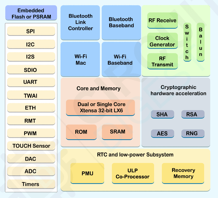
The above image represents the functional block diagram of a ESP32 SoC.
Display for Smartwatch
As mentioned earlier, I have considered two displays for the project. 1.28” round TFT display with GC9A01 controller and 1.69” rounded corner rectangular display with ST7789V controller. Both are excellent IPS Panel displays with a resolution of 240x240 pixels (GC9A01) and 240x280 (ST7789V). I chose the 1.69” Square display for the project.
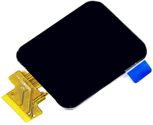
The display has a high density of 220 ppi, and 280x240 full-color pixels with IPS any-angle viewing. Since the display uses 4-wire SPI to communicate and has its own pixel-addressable frame buffer, it can be used with every kind of microcontroller. Not only that, the SPI interface reduces the number of pins needed to interface the display. The display uses the popular ST7789V controller. ST7789V’s frame buffer can hold the display data up to 240x320x18 bits.
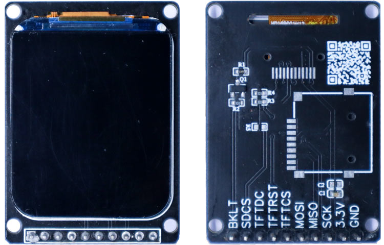
The display has an outline dimension of 30.07x37.43x1.56 mm and an active area of 27.97x32.63 mm. It comes with a 12-pin interface that uses the SPI bus for communication. For testing purposes, I will be using a break-out board with bare minimum components.
Now as we selected this specific display, let’s test it with the ESP32 and Arduino IDE. The testing procedure and schematics for the same are given below.
Circuit Diagram to Interface TFT Display with ESP32
Before going any further let’s connect the display to ESP32 devkit and test. For testing, connect the display module to the ESP32 Devkit as per the Circuit diagram below. Connections are pretty simple; we only have to connect the SPI pins along with the power and backlight control pins.

Make sure the VCC is connected to the 3.3V line. The display is only 3.3V tolerant, so connecting it to the 5V supply or 5V logic will destroy the display.
[Img]
I have made a simple PCB as per the schematics given above. It is not necessary to make one, you can simply make the connection on a breadboard with jumper cables.
Testing the Display
To interface the display with the ESP32, we are going to use the TFT_eSPI library. Since the default library doesn’t contain the configurations for our display’s specific resolution, we are going to use a modified version. You can also use the official one with necessary modifications. For ease of use, we have uploaded the modified versions to the Circuit Digest GitHub Repo. You can download the modified library from the GitHub repo mentioned at the bottom of this article. Once downloaded, extract and copy the TFT_eSPI library folder to the Arduino library folder.
Once all the connections are made and the library is files copied, open the Arduino IDE and open any TFT_eSPI example codes from the examples menu. I choose the TFT-Meter Example from Examples -> TFT_eSPI -> 320x240 -> TFT-Meter, since the example looks really good and the animations are so smooth. You can see that in the below GIF.
Testing Some Watch Faces
Since we are going to use the internal RTC of the ESP32, we will need one more library. You need to install the ESP32Time library. It is also included in the GitHub repo. Either you can use the included one or you can install it through the library manager. Once it’s done, compile the watch face example code and upload it to the ESP32. The example will cycle through some interesting watch face designs. You can see them below.
Complete Project Code
#include <SPI.h>
#include <TFT_eSPI.h> // Hardware-specific library
#include <ESP32Time.h>
#include "fonts.h"
#include "Casio.h"
//ESP32Time rtc;
ESP32Time rtc(3600);  // offset in seconds GMT+1
#define TFT_GREY 0x5AEB
#define TFT_SKYBLUE 0x067D
#define color1 TFT_WHITE
#define color2  0x8410//0x8410
#define color3 0x5ACB
#define color4 0x15B3
#define color5 0x00A3
#define background 0xB635
TFT_eSPI tft = TFT_eSPI();       // Invoke custom library
TFT_eSprite img = TFT_eSprite(&tft);
float sx = 0, sy = 1, mx = 1, my = 0, hx = -1, hy = 0;    // Saved H, M, S x & y multipliers
float sdeg = 0, mdeg = 0, hdeg = 0;
uint16_t osx = 120, osy = 140, omx = 120, omy = 140, ohx = 120, ohy = 140; // Saved H, M, S x & y coords
uint16_t x0 = 0, x1 = 0, yy0 = 0, yy1 = 0;
uint32_t targetTime = 0;                    // for next 1 second timeout
static uint8_t conv2d(const char* p); // Forward declaration needed for IDE 1.6.x
uint8_t hh = conv2d(__TIME__), mm = conv2d(__TIME__ + 3), ss = conv2d(__TIME__ + 6); // Get H, M, S from compile time
unsigned long lastfacechange = 0;
bool initial = 1;
volatile int counter = 0;
float VALUE;
float lastValue = 0;
int lastsec = 0;
double rad = 0.01745;
float x[360];
float y[360];
int watchface = 0;
bool facechange = false;
float px[360];
float py[360];
float lx[360];
float ly[360];
int r = 104;
int ssx = 120;
int ssy = 140;
String cc[12] = {"45", "40", "35", "30", "25", "20", "15", "10", "05", "0", "55", "50"};
String days[] = {"SUNDAY", "MONDAY", "TUESDAY", "WEDNESDAY", "THURSDAY", "FRIDAY", "SATURDAY"};
String days1[] = {"SUN", "MON", "TUE", "WED", "THU", "FRI", "SAT"};
int start[12];
int startP[60];
const int pwmFreq = 5000;
const int pwmResolution = 8;
const int pwmLedChannelTFT = 0;
int angle = 0;
bool onOff = 0;
bool debounce = 0;
String h, m, s, d1, d2, m1, m2;
void setup(void) {
  rtc.setTime(ss, mm, hh, 26, 7, 2022);  // 26th Jjuly 2022 compile date
  tft.init();
  tft.setRotation(0);
  //tft.fillScreen(TFT_BLACK);
  //tft.fillScreen(TFT_RED);
  //tft.fillScreen(TFT_GREEN);
  //tft.fillScreen(TFT_BLUE);
  //tft.fillScreen(TFT_BLACK);
  tft.setSwapBytes(true); //*/
  tft.fillScreen(TFT_BLACK);
  img.setColorDepth(8);
  img.setSwapBytes(true);
  img.createSprite(240, 280);
  img.setTextDatum(4);
  targetTime = millis() + 1000;
  facechange = true;
}
int lastAngle = 0;
float circle = 100;
bool dir = 0;
int rAngle = 359;
void loop() {
  if (millis() - lastfacechange > 10000)
  {
    watchface++;
    if (watchface > 3)
    {
      watchface = 0;
    }
    facechange = true;
  }
  if (facechange)
  {
    tft.fillScreen(TFT_BLACK);
    if (watchface == 1)
    {
      tft.pushImage(0, 0, 240, 280, Casio2);
      tft.setTextColor(0x0081, background);
      tft.fillRoundRect(48, 127, 128, 48, 5, background);
    }
    else if (watchface == 2)
    {
      tft.pushImage(0, 0, 240, 280, Casio1);
      tft.setTextColor(0x0081, background);
      tft.fillRoundRect(48, 127, 128, 48, 5, background);
    }
    facechange = false;
    lastfacechange = millis();
  }
  if (watchface == 0)
  {
    int b = 0;
    int b2 = 0;
    for (int i = 0; i < 360; i++)
    {
      x[i] = (r * cos(rad * i)) + ssx;
      y[i] = (r * sin(rad * i)) + ssy;
      px[i] = ((r - 16) * cos(rad * i)) + ssx;
      py[i] = ((r - 16) * sin(rad * i)) + ssy;
      lx[i] = ((r - 26) * cos(rad * i)) + ssx;
      ly[i] = ((r - 26) * sin(rad * i)) + ssy;
      if (i % 30 == 0) {
        start[b] = i;
        b++;
      }
      if (i % 6 == 0) {
        startP[b2] = i;
        b2++;
      }
    }
    rAngle = rAngle - 2;
    angle = rtc.getSecond() * 6;
    s = String(rtc.getSecond());
    m = String(rtc.getMinute());
    h = String(rtc.getHour());
    if (m.toInt() < 10)
      m = "0" + m;
    if (h.toInt() < 10)
      h = "0" + h;
    if (s.toInt() < 10)
      s = "0" + s;
    if (rtc.getDay() > 10)
    {
      d1 = rtc.getDay() / 10;
      d2 = rtc.getDay() % 10;
    }
    else
    {
      d1 = "0";
      d2 = String(rtc.getDay());
    }
    if (rtc.getMonth() > 10)
    {
      m1 = rtc.getMonth() / 10;
      m2 = rtc.getMonth() % 10;
    }
    else
    {
      m1 = "0";
      m2 = String(rtc.getMonth());
    }
    if (angle >= 360)
      angle = 0;
    if (rAngle <= 0)
      rAngle = 359;
    if (dir == 0)
      circle = circle + 0.5;
    else
      circle = circle - 0.5;
    if (circle > 140)
      dir = !dir;
    if (circle < 100)
      dir = !dir;
    if (angle > -1)
    {
      lastAngle = angle;
      VALUE = ((angle - 270) / 3.60) * -1;
      if (VALUE < 0)
        VALUE = VALUE + 100;
      img.fillSprite(TFT_BLACK);
      img.fillCircle(ssx, ssy, 124, color5);
      img.setTextColor(TFT_WHITE, color5);
      img.drawString(days[rtc.getDayofWeek()], circle, 140, 2);
      for (int i = 0; i < 12; i++)
        if (start[i] + angle < 360) {
          img.drawString(cc[i], x[start[i] + angle], y[start[i] + angle], 2);
          img.drawLine(px[start[i] + angle], py[start[i] + angle], lx[start[i] + angle], ly[start[i] + angle], color1);
        }
        else
        {
          img.drawString(cc[i], x[(start[i] + angle) - 360], y[(start[i] + angle) - 360], 2);
          img.drawLine(px[(start[i] + angle) - 360], py[(start[i] + angle) - 360], lx[(start[i] + angle) - 360], ly[(start[i] + angle) - 360], color1);
        }
      img.setFreeFont(&DSEG7_Modern_Bold_20);
      img.drawString(s, ssx, ssy - 36);
      img.setFreeFont(&DSEG7_Classic_Regular_28);
      img.drawString(h + ":" + m, ssx, ssy + 28);
      img.setTextFont(0);
      img.fillRect(70, 86, 12, 20, color3);
      img.fillRect(84, 86, 12, 20, color3);
      img.fillRect(150, 86, 12, 20, color3);
      img.fillRect(164, 86, 12, 20, color3);
      img.setTextColor(0x35D7, TFT_BLACK);
      img.drawString("MONTH", 84, 78);
      img.drawString("DAY", 162, 78);
      img.setTextColor(TFT_SKYBLUE, TFT_BLACK);
      img.drawString("Circuit Digest", 120, 194);
      img.drawString("***", 120, 124);
      img.setTextColor(TFT_WHITE, color3);
      img.drawString(m1, 77, 96, 2);
      img.drawString(m2, 91, 96, 2);
      img.drawString(d1, 157, 96, 2);
      img.drawString(d2, 171, 96, 2);
      for (int i = 0; i < 60; i++)
        if (startP[i] + angle < 360)
          img.fillCircle(px[startP[i] + angle], py[startP[i] + angle], 1, color1);
        else
          img.fillCircle(px[(startP[i] + angle) - 360], py[(startP[i] + angle) - 360], 1, color1);
      img.fillTriangle(ssx - 1, ssy - 70, ssx - 5, ssy - 56, ssx + 4, ssy - 56, TFT_ORANGE);
      img.fillCircle(px[rAngle], py[rAngle], 6, TFT_RED);
      img.pushSprite(0, 0);
    }
  }
  else if (rtc.getSecond() != lastsec)
  {
    if (watchface == 1 || watchface == 2)
    {
      String med;
      if (rtc.getSecond() % 2) {
        med = ":";
      }
      else
      {
        med = " " ;
      }
      tft.setFreeFont(&DSEG7_Classic_Bold_30);
      if (rtc.getHour() > 10 && rtc.getMinute() > 10)
      {
        tft.drawString(String(rtc.getHour()) + ":" + String(rtc.getMinute()), 46, 136);
      }
      else if (rtc.getHour() < 10 && rtc.getMinute() > 10)
      {
        tft.drawString("0" + String(rtc.getHour()) + ":" + String(rtc.getMinute()), 46, 136);
      }
      else if (rtc.getHour() > 10 && rtc.getMinute() < 10)
      {
        tft.drawString(String(rtc.getHour()) + ":0" + String(rtc.getMinute()), 46, 136);
      }
      else
      {
        tft.drawString("0" + String(rtc.getHour()) + ":0" + String(rtc.getMinute()), 46, 146);
      }
      tft.setFreeFont(&DSEG7_Classic_Bold_20);
      if (rtc.getSecond() < 10)
      {
        tft.drawString("0" + String(rtc.getSecond()), 154, 146);
      }
      else
      {
        tft.drawString(String(rtc.getSecond()), 154, 146);
      }
      tft.setFreeFont(&DSEG14_Classic_Bold_18);
      tft.drawString(days1[rtc.getDayofWeek()], 94, 106);
      tft.drawString(String(rtc.getDay()), 156, 106);
    }
    else if (watchface == 3)
    {
      img.setTextColor(TFT_WHITE, TFT_BLACK);  // Adding a background colour erases previous text automatically
      // Draw clock face
      img.fillCircle(120, 140, 118, TFT_GREEN);
      img.fillCircle(120, 140, 110, TFT_BLACK);
      // Draw 12 lines
      for (int i = 0; i < 360; i += 30) {
        sx = cos((i - 90) * 0.0174532925);
        sy = sin((i - 90) * 0.0174532925);
        x0 = sx * 114 + 120;
        yy0 = sy * 114 + 140;
        x1 = sx * 100 + 120;
        yy1 = sy * 100 + 140;
        img.drawLine(x0, yy0, x1, yy1, TFT_GREEN);
      }
      // Draw 60 dots
      for (int i = 0; i < 360; i += 6) {
        sx = cos((i - 90) * 0.0174532925);
        sy = sin((i - 90) * 0.0174532925);
        x0 = sx * 102 + 120;
        yy0 = sy * 102 + 140;
        // Draw minute markers
        img.drawPixel(x0, yy0, TFT_WHITE);
        // Draw main quadrant dots
        if (i == 0 || i == 180) img.fillCircle(x0, yy0, 2, TFT_WHITE);
        if (i == 90 || i == 270) img.fillCircle(x0, yy0, 2, TFT_WHITE);
      }
      img.fillCircle(120, 141, 3, TFT_WHITE);
      // Pre-compute hand degrees, x & y coords for a fast screen update
      sdeg = rtc.getSecond() * 6;                // 0-59 -> 0-354
      mdeg = rtc.getMinute() * 6 + sdeg * 0.01666667; // 0-59 -> 0-360 - includes seconds
      hdeg = rtc.getHour() * 30 + mdeg * 0.0833333; // 0-11 -> 0-360 - includes minutes and seconds
      hx = cos((hdeg - 90) * 0.0174532925);
      hy = sin((hdeg - 90) * 0.0174532925);
      mx = cos((mdeg - 90) * 0.0174532925);
      my = sin((mdeg - 90) * 0.0174532925);
      sx = cos((sdeg - 90) * 0.0174532925);
      sy = sin((sdeg - 90) * 0.0174532925);
      if (rtc.getSecond() == 0 || initial) {
        initial = 0;
        // Erase hour and minute hand positions every minute
        img.drawLine(ohx, ohy, 120, 141, TFT_BLACK);
        ohx = hx * 62 + 121;
        ohy = hy * 62 + 141;
        img.drawLine(omx, omy, 120, 141, TFT_BLACK);
        omx = mx * 84 + 120;
        omy = my * 84 + 141;
      }
      // Redraw new hand positions, hour and minute hands not erased here to avoid flicker
      img.drawLine(osx, osy, 120, 141, TFT_BLACK);
      osx = sx * 90 + 121;
      osy = sy * 90 + 141;
      img.drawLine(osx, osy, 120, 141, TFT_RED);
      img.drawLine(ohx, ohy, 120, 141, TFT_WHITE);
      img.drawLine(omx, omy, 120, 141, TFT_WHITE);
      img.drawLine(osx, osy, 120, 141, TFT_RED);
      img.fillCircle(120, 141, 3, TFT_RED);
      img.pushSprite(0, 0);
    }
    lastsec = rtc.getSecond();
  }
}
static uint8_t conv2d(const char* p) {
  uint8_t v = 0;
  if ('0' <= *p && *p <= '9')
    v = *p - '0';
  return 10 * v + *++p - '0';
}
Comments
Finally got the Adafruit 1…
Finally got the Adafruit 1.69" 280x240 Round Rectangle Color IPS TFT Display - ST7789 to work with the ESP32 board. Look for the project on the Adafruit site using this display. They use their own board, but it work with a regular ESP32-WROVER-E board. The secret was to use the default SPI pins without specifying them in code, and using their Adafruit_GFX, Adafruit_ST7789, SdFat, and Adafruit_ImageReader libraries.
Still haven't got the watch faces going yet. Soon.
Finally got the watch face…
Finally got the watch face code to work. The downloaded modified library didn't work for my display, but once I figured out how to modify the library to fit my display and ESP32 pins, which took quite a while, I got many of the library examples to work and finally the watch faces displayed. It's a beautiful display, and the sample watch faces look great, but not touch sensitive. So if I continue with this display I'll have to use switches. On to part two. CU
Hi Tony, how is your project…
Hi Tony, how is your project coming?
Hi everyone. Does that 1.69"…
Hi everyone. Does that 1.69" rounded display has a touchscreen?
Hi, did you add any chips…
Hi,
did you add any chips between the bare 1.69" TFT and your PCB? because what I bought 1.69" with FPC cable doesn't have MOSI pin?
Hi, no there is no chip…
Hi, no there is no chip between the TFT and PCB. If the display you bought doesn't mention a MOSI pin, you may check for DI or Din pin. share the pic of the display If possible.

I couldn't find the display from this article so I purchased one from Adafruit.
It was a 1.69" 280x240 Round Rectangle Color IPS TFT Display - ST7789.
I got it to work all right with code from the Adafruit site using an Arduino and the Arduino-ST7735 library.
However I can't get it to work with an ESP32 and any of the examples or the watch face code using the TFT_eSPI.h library.
Does anyone have any idea on how to get the code to work with the Adafruit display?
Thanks.