

Every engineer and hobbyist nowadays has a workbench for all of their tools and gadgets, and if you're a 3D printing enthusiast, you've probably used the vernier calliper a lot. This emphasizes the significance of precise measurement tools in engineering. After having used many of them throughout our lives, it is now time for us to attempt to build one. In this project, we will be making a distance measuring wheel using a rotary encoder that can help us measure the length it traverses with millimeter-level accuracy.
Components Required:
- Arduino Pro Mini
- USB To TTL Module (For Programming the Pro-Mini)
- Rotary Encoder (With High Pulse Per Revolution)
- Li-Po Battery 700mAh
- TP4056 Module
- Push-Switch
- SPST Toggle Switch
How The DIY Digital Measuring Wheel Works:
This project used the basic principles of a rotary encoder. You can refer to the article for a more comprehensive understanding of the rotary encoder. The work of our rotary encoder is that it converts the rotation of the shaft into a series of pulses. The encoder gives out two pulses which are at a phase difference of 90 degrees, by evaluating these two phases we can easily determine the direction of rotation of the module.
Along with these, we need to have a simple push switch that acts as the reset button, using a signal from the reset button we can decrease the counter. To control all our modules, we will be using an Arduino Pro-Mini. This will act as our main controller to process the pulses from the rotary encoder and display the measured value on the OLED Display via the SPI Protocol.
DIY Digital Measuring Wheel Connection Diagram

The diagram shows the li-po battery connected to the TP4056 module that is then connected with a switch and powers all the components in the circuit.
The OLED Module, Rotary Encoder, and the push switch are connected to the Arduino Pro Mini to the following pins.
Push Switch, connected to pin 3 to use the interrupt functionality of the pro mini
Rotary Encoder, one phase connected to Pin 2 of the pro mini to exploit the interrupt functionality, second phase connected to Pin 6 acting as a simple digital read.
0.96” OLED Display, Connected with pins 8, 9, 10, 12, and 13 in the SPI Configuration.
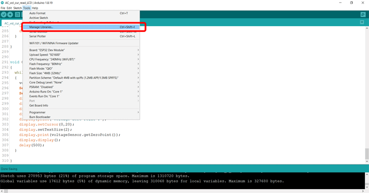
Code for the Arduino Digital Measuring Wheel
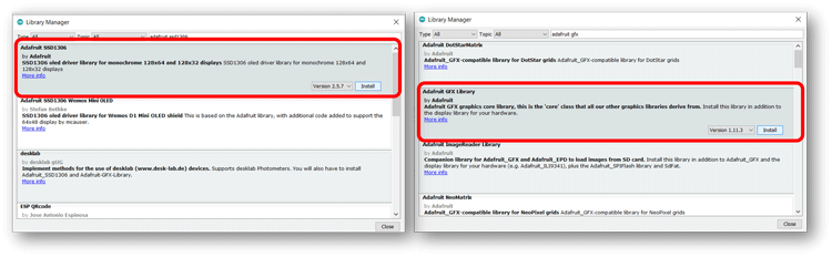
Although our rotary encoder does not require the use of any library, to operate the OLED Module, we will need the Adafruit OLED Libraries. We start by installing the Adafruit GFX and the Adafruit SSD 1306 Library. Simply by clicking on the library manager in the Tools menu in the Arduino IDE.
We search for Adafruit GFX and Adafruit SSD1306 and simply install them by clicking on the install button.
Once the libraries are installed, we can simply include them in our code in the beginning.
#include <SPI.h>
#include <Wire.h>
#include <Adafruit_GFX.h>
#include <Adafruit_SSD1306.h>
After this, we initialize the OLED pin and define pins for our rotary encoder’s output phases as well as the reset push switch.
#define OLED_MOSI  12
#define OLED_CLK   13
#define OLED_DC    9
#define OLED_CS    10
#define OLED_RESET  8
Adafruit_SSD1306 display(SCREEN_WIDTH, SCREEN_HEIGHT,
  OLED_MOSI, OLED_CLK, OLED_DC, OLED_RESET, OLED_CS);
#define outputA 2
#define outputB 6
#define SetZero 3
Now we define the constants on our device, the diameter of our rotary disc, and the counts per revolution (CPR) of each phase of our encoder. Since we will be mounting a disc of 70mm diameter onto the rotary encoder shaft, we set Diameter as 70.
Observing from the data sheet of our rotary encoder, we know that each phase sends 400 pulses per revolution, since each pulse will have two transitions, we get a count of 800 (400X2). Thus we enter the CPR as 800.
We also define a variable called factor which is actually the distance moved with every count. We will later multiply this factor by the count calculated by the controller.
#define Diameter 70 //in mm
#define CPR 800 //Counts per revolution of each phase.
float factor= (3.1415*Diameter)/(CPR);
We now declare some extra variables that will be required during the working of the code.
bool aState;
bool aLastState;
unsigned long int lastdata=0;
unsigned long int lastDisplay=0;
bool led=0;
long units=0;
bool i=0;
In the void setup function, we simply need to enable the input pins with pull-ups. Declare the interrupt pins and the interrupt functions, initialize the OLED Display and start displaying the measurement as zero.
void setup() {
  pinMode (outputA,INPUT_PULLUP);
  pinMode (outputB,INPUT_PULLUP);
  pinMode (SetZero,INPUT_PULLUP);
  attachInterrupt(digitalPinToInterrupt(2),ISR1,CHANGE);
  attachInterrupt(digitalPinToInterrupt(3),ISR2,FALLING);
  Serial.begin(9600);
  if(!display.begin(SSD1306_SWITCHCAPVCC)) {
    Serial.println(F("SSD1306 allocation failed"));
    for(;;); // Don't proceed, loop forever
  }
  // Clear the buffer
  display.clearDisplay();
  display.display();
  display.setTextColor(WHITE);
  aLastState = PIND&(1<<2)?1:0;
        display.clearDisplay();
        display.setTextSize(2);
        displayCenter("Distance",2);
        display.setTextSize(3);
        displayCenter(String(units),30);
        lastDisplay=millis();
}
In the void loop function of this code, we perform very little functionality mostly because most work is done in the Interrupt Functions as well as the updateDisplay() function. We use a variable i as a flag that gets set to one whenever there is a pulse generated by the rotary encoder or when we reset the counter variable. In the void loop function, we call the updateDisplay() function only when the flag variable i is 1.
Along with this we also implement a simple code using a lastData variable and the millis() function to reset the counter back to zero in case there is no input for the last 10 seconds.
void loop() {
    if(i==1)
    {
      updateDisplay();
    }
   if(millis()-lastdata>10000) {
     units=0;
     updateDisplay();
     lastdata=millis();
   }
}
Since we connected one phase of the rotary encoder output on pin 2 of the Pro-Mini, ISR1 is executed each time there is a transition in value. From the working of rotary encoders, we know that if the phases are unequal the encoder is rotating counter-clockwise, we hence decrease the counter value, and if the phases are equal we increase the counter value.
Notice that instead of using a simple digitalRead() function, we have used the statement bool(PIND&(1<<6)). This command is used to directly read the complete port D and use only the 6th bit (for pin 6) for our evaluation purpose.
void ISR1() {
  if ( bool(PIND&(1<<6)) != bool(PIND&(1<<2)) )
     {
       units --;
     }
     else
     {
       units ++;
     }
     i=1;
}
The Push switch is connected to pin 3 which executes the second Interrupt, ISR2. This function simply resets the counter variable to zero.
void ISR2() {
  units=0;
  i=1;
}
Finally we have the updateDisplay() and the displayCenter() functions. The updateDisplay() function is simply used to clear the OLED Screen and display the new value of the distance measured. This function only updates the display every 500 milliseconds to conserve CPU Resources and ensure that we do not miss any pulses from the encoder. This also prevents screen flickering.
The displayCenter() function as the name suggests, aligns the text in the horizontal center of the screen.
void updateDisplay() {
        if(millis() - lastDisplay>500)
        {
        display.clearDisplay();
        display.setTextSize(2);
        displayCenter("Distance",2);
        display.setTextSize(3);
        displayCenter(String(float(units*factor)),30);
        lastDisplay=millis();
        lastdata = lastDisplay;
        i=0;
        }
}
void displayCenter(String text, int line)
{
  int16_t x1;
  int16_t y1;
  uint16_t width;
  uint16_t height;
  display.getTextBounds(text, 0, 0, &x1, &y1, &width, &height);
  // display on horizontal center
  display.setCursor((SCREEN_WIDTH - width) / 2, line);
  display.println(text); // text to display
  display.display();
}
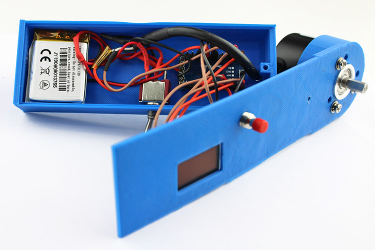
Assembly of the DIY Arduino Measuring Wheel
A 3d printed enclosure has been designed for the project, the STL files of the enclosure are attached. The electronics are to be fitted in the box as shown below.
The Disc is to be attached to the shaft of the rotary encoder.
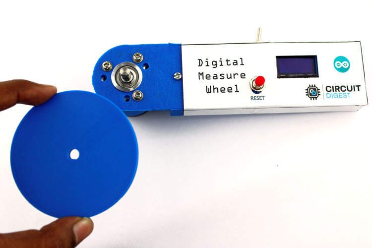
Once this is done, our project is complete and we can use our Digital Measuring Wheel to measure the length of objects accurately. You can also put indicators on the disc using a black permanent marker for ease of use.
Complete Project Code
#include <SPI.h>
#include <Wire.h>
#include <Adafruit_GFX.h>
#include <Adafruit_SSD1306.h>
#define SCREEN_WIDTH 128 // OLED display width, in pixels
#define SCREEN_HEIGHT 64 // OLED display height, in pixels
// Declaration for SSD1306 display connected using software SPI (default case):
#define OLED_MOSI  12
#define OLED_CLK   13
#define OLED_DC    9
#define OLED_CS    10
#define OLED_RESET  8
Adafruit_SSD1306 display(SCREEN_WIDTH, SCREEN_HEIGHT,
  OLED_MOSI, OLED_CLK, OLED_DC, OLED_RESET, OLED_CS);
#define outputA 2
#define outputB 6
#define SetZero 3
#define Diameter 70 //in mm
#define CPR 800 //Counts per revolution of each phase.
float factor= (3.1415*Diameter)/(CPR);
bool aState;
bool aLastState;
unsigned long int lastdata=0;
unsigned long int lastDisplay=0;
bool led=0;
long units=0;
bool i=0;
void setup() {
  pinMode (outputA,INPUT_PULLUP);
  pinMode (outputB,INPUT_PULLUP);
  pinMode (SetZero,INPUT_PULLUP);
  attachInterrupt(digitalPinToInterrupt(2),ISR1,CHANGE);
  attachInterrupt(digitalPinToInterrupt(3),ISR2,FALLING);
  Serial.begin(9600);
  if(!display.begin(SSD1306_SWITCHCAPVCC)) {
    Serial.println(F("SSD1306 allocation failed"));
    for(;;); // Don't proceed, loop forever
  }
  // Clear the buffer
  display.clearDisplay();
  display.display();
  display.setTextColor(WHITE);
  aLastState = PIND&(1<<2)?1:0;
        display.clearDisplay();
        display.setTextSize(2);
        displayCenter("Length(mm)",15);
        display.setTextSize(3);
        displayCenter(String(units),42);
        lastDisplay=millis();
}
void loop()
{
    if(i==1)
    {
      updateDisplay();
    }
   if(millis()-lastdata>10000)
   {
     units=0;
     updateDisplay();
     lastdata=millis();
   }
}
void ISR1()
{
  if ( bool(PIND&(1<<6)) != bool(PIND&(1<<2)) )
     {
       units --;
     }
     else
     {
       units ++;
     }
     i=1;
}
void ISR2()
{
  units=0;
  i=1;
  }
void updateDisplay()
{
        if(millis() - lastDisplay>500)
        {
        display.clearDisplay();
        display.setTextSize(2);
        displayCenter("Length(mm)",15);
        display.setTextSize(3);
        displayCenter(String(float(units*factor)),42);
        lastDisplay=millis();
        lastdata = lastDisplay;
         i=0;
        }
  }
void displayCenter(String text, int line)
{
  int16_t x1;
  int16_t y1;
  uint16_t width;
  uint16_t height;
  display.getTextBounds(text, 0, 0, &x1, &y1, &width, &height);
  // display on horizontal center
  display.setCursor((SCREEN_WIDTH - width) / 2, line);
  display.println(text); // text to display
  display.display();
}Comments
I have another question if I…
I have another question if I may. Since the STJ file is tailored to the dimensions of the rotary encoder, would it be possible to get the exact specifications of the rotary encoder. ( Make and model)
Thanks again
Robert
I look forward to…
I look forward to duplicating your project. Please post the STL files for the measuring device. Thanks!

Greetings,
This looks like a very interresting project. Although I am novice at this type of project, this is definitely something I would like to try. You mentioned that the STL files for the casing were attached... I'm sorry but they're nowhere to be found. Could you please provide a link.
Thanks
Robert