

There are several soil monitor sensors available that can be easily interfaced with the Arduino or other Embedded modules and can be programmed for different types of projects such as Smart Agriculture Monitoring System. The problem is not having a combined, retrofit module that can easily be used in different projects or applications as needed. In this project, we will build a low-cost connected solution with a pre-designed Soil monitor using different components. This elegant project design was made possible by the PCB boards fabricated by PCBWay, we will also show you how the board was designed and ordered from PCBway. If you are a complete beginner to soil moisture sensor you can check out how to use soil moisture sensor with Arduino and understand the basics before you proceed with this tutorial.
In this project, our planning will be to achieve the following things -
- Having Soil sensor and the Microcontroller on a single board.
- 18650 Lithium battery-based system
- Reverse Polarity Protection for the battery
- USB Port to program, get a log or charge the battery
- Low power consumption
- Wi-Fi Connectivity
- Small size to be fit inside a 3D printed enclosure
- A ready to use and ready to manufacturing product
- Design the PCB
- Ability to increase the Soil probe current.
You can check out the Full Demonstration of the Soil Moisture Monitroing Device over here:
Components Required for Building a Soil Moisture Monitoring Device
The full BOM is given in the below list-
|
Qty |
Value |
Package |
Parts |
|
1 |
Pin Header - 0.254" |
1X02 |
JP1 |
|
1 |
Jumper - 0.254" |
||
|
1 |
.1uF/50v |
C0603 |
C5 |
|
1 |
0.1uF / 6.3V |
C0603 |
C1 |
|
1 |
0.1uF / 6.3V |
C0805 |
C8 |
|
1 |
0R |
R0805 |
R6 |
|
1 |
1.25k |
R0603 |
R9 |
|
1 |
100R |
R0805 |
R11 |
|
1 |
100k |
M0805 |
R14 |
|
2 |
10k |
R0603 |
R12, R13 |
|
1 |
10k |
R0805 |
R10 |
|
1 |
10uF |
C0805 |
C4 |
|
1 |
10uF / 6.3V |
C0805 |
C7 |
|
4 |
12k |
M0805 |
R1, R2, R3, R4 |
|
1 |
12k |
R0805 |
R5 |
|
1 |
18650 BATTERY HOLDER |
HOLDER |
BAT1 |
|
2 |
2.2uFuF / 6.3V |
C0805 |
C2, C3 |
|
1 |
22.1k |
R0603 |
R15 |
|
1 |
2N3904 |
SOT23 |
Q1 |
|
1 |
2k |
R0603 |
R17 |
|
1 |
330R |
R0603 |
R8 |
|
1 |
47.5k |
R0603 |
R16 |
|
1 |
470pF/10V |
C0805 |
C6 |
|
1 |
629105136821 |
USB-MICRO |
J1 |
|
1 |
680R |
R0603 |
R7 |
|
1 |
ESP-12E/F |
ESP-12E |
IC1 |
|
1 |
LTC4054ES5-4.2#TRMPBF |
SOT95P280X100-5N |
U1 |
|
1 |
MIC5219-3.3YM5 |
SOT23-5 |
IC3 |
|
2 |
RED LED |
CHIPLED_0805 |
LED1, LED2 |
|
1 |
SILABS_CP210 |
SILABS_MLP28 |
IC2 |
|
2 |
SKRPABE010 |
SKRPABE010 |
SW1, SW2 |
|
1 |
SRV05 |
SC-74 |
D1 |
|
1 |
SS14 |
DO-214AC |
D2 |
|
2 |
SS8050 |
SOT23 |
T1, T2 |
|
1 |
Si2301 |
SOT23-3 |
Q2 |
Smart Plant Monitoring Device Circuit Diagram
The complete schematic for the smart soil moisture monitoring Device is given below:

Let's see how the components are connected. For better understanding, each section of the schematic is separated as a block as per the working principle of each major component.
Application Controller
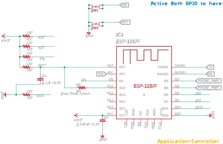
This is the ESP-12 microcontroller that is programmed by the programmer. It is a widely popular, low-cost, WiFi-based microcontroller that has multiple pins. The R6 is a 0R Jumper used to activate the deep sleep mode. It has 4 resistors for the pull-up in the IO0, IO2, EN, and RST Pins. The C1 and R4 are used to make a time delay circuit for proper reset in each reset state or Power ON mode. It also has a pull-down resistor in the IO15. The Soil probe is connected in the two pins, IO5 and IO4. TX and RX are connected further to the UART to USB bridge. The SW1 and SW2 are used for the RST and Boot mode. It has an ADC pin and is used to measure the changes in the Soil Probe depending on the changes of the Soil Moisture.
The Sensor Probe
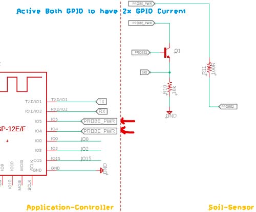
The Soil Monitor has two pins, IO5 and IO4. These two pins together will provide a double current (25mA x 2 = 50mA). Since the current difference can be very less, it will drive a transistor to provide a large number of changes and the output will be sensed by the ADC. This circuit is taken from the SparkFun Soil Probe.
USB to UART
Here, the RX-TX needs to be converted to the USB port. This is required to program the module and also for getting the required LOG in the UART terminal during development time. For this, we used the widely popular CP2102 Module.
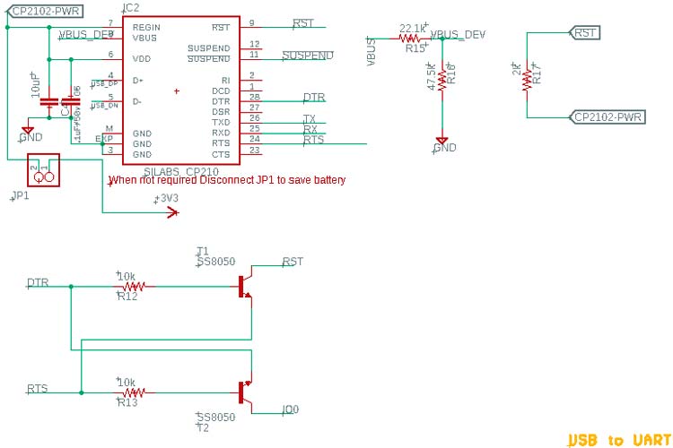
There is a Jumper that is used to disconnect the CP2102 and its circuitry from the Power rail to save battery when the Probe is used in the application and not for development purposes. However, irrespective of the RST, BOOT switches, an auto configurable logic using a transistor is set here to program the board with an autoboot and reset feature.
The USB Input Section
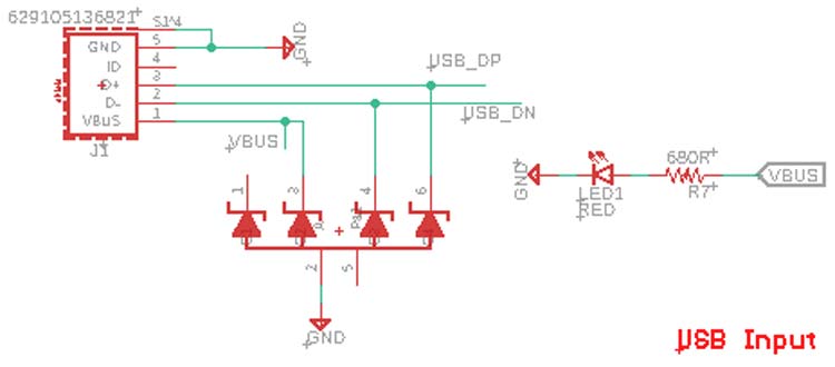
This USB input section has proper ESD protection to save the device from ESD surges. The USB connector used here is 629105136821. This is the part number Wurth Elektronic Micro USB Port. An equivalent USB port can also be used here since the package is generic. An LED is used here to provide information about the availability of USB Power.
Battery Charging Section
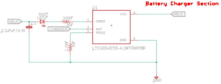
An Analog devices IC, LTC4054ES5-4.2#TRMPBF is used to charge the lithium battery. This is an 800mA, 4.2V battery charger. The resistor R9 is used to provide 800mA of charge current to the battery. An LED on the charge status pin indicates the charging status. During the Charging period, it will glow constantly. It will stop glowing when the battery charging is completed.
Voltage Regulator
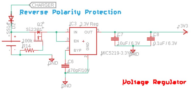
As we are using a 3.3V logic level controller and the battery we are using has a voltage range of 3.7V nominal, 4.2V maximum, we need a voltage regulator to get the output. Here, we are using MIC5219-3.3V. The reason we have chosen this IC is that it is having 500mA of current capability, a tight load, line regulation, a very low dropout, along with 500mV at 500mA of output, and ultra-low noise regulator feature. This is easily available and also very low-cost LDO and perfect for this.
Another major thing is reverse Polarity protection. For that, we have used a high-Power P-channel MOSFET to provide the no drop reverse polarity protection. This MOSFET which is the Q2 will only turn ON if the battery is connected properly. If the battery is inserted in the reverse direction, the Q2 will be turned off and disconnect the entire circuitry from the battery. Additionally, D2 is used to protect the reverse current flow into the charger, when the USB is not plugged in, the Battery leakage current will significantly decrease. The Drop voltage of this diode will obviously affect the charging characteristic, but since it will rarely be used due to high battery backup, it is OK to compensate for that.
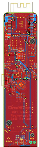
Fabricating the PCB for Plant Monitoring Device
Well, the PCB Design is done with the below specification -
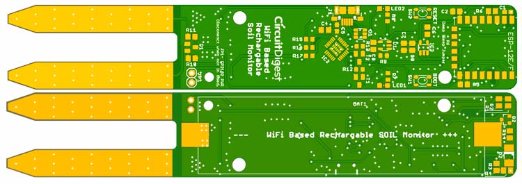
In the above, the 2D image of the PCB is shown.
Special attention is needed on the Sensor Probe section -
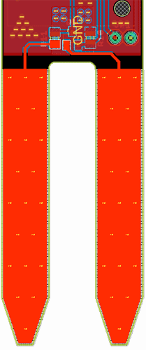
The solder mask layer is removed in this section on both Top and Bottom layers. Multiple vias are stitched together to provide proper connectivity on both layers. It is advisable and also, if possible, due to this section, to make this PCB in gold plating. In such a case, the connectivity will be increased due to the low resistance path of the Au mask. However, that will increase the PCB price by a significant amount. For the prototype and testing purposes, we used a simple solder mask SnPb.
Also, it is advisable not to use lower than 35um copper thickness for this PCB.
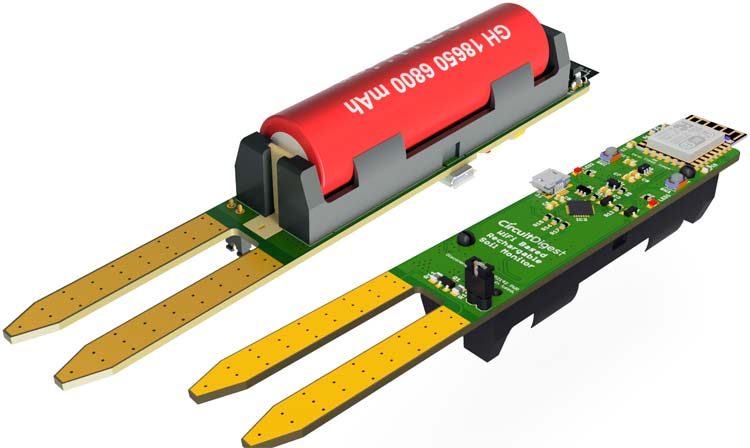
We have also used proper thickness for the 3.3V trace as per the IPC standard to compensate for the 500mA of current flow. Since Our Battery traces as well as the USB input is capable of providing 800mA of current, we considered that too for the VUSB (5V input) and the Battery traces. Eventually, we made the 3D files and exported the STEP before making the actual PCB understand if everything is correctly placed and is ready to fit inside the enclosure.
Kindly ignore the Battery capacity, it is only for illustration purposes.
Ordering PCB from PCBWay
Now after finalizing the design, you can proceed with ordering the PCB:
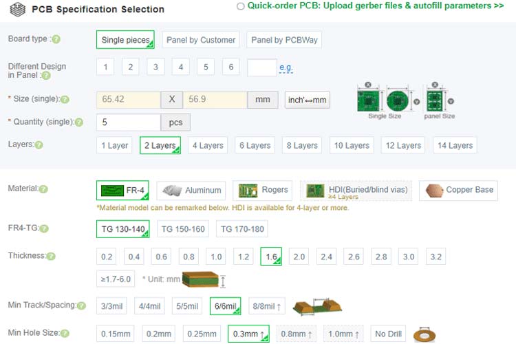
Step 1: Get into PCBWay Website, sign up if this is your first time. Then, in the PCB Prototype tab, enter the dimensions of your PCB, the number of layers, and the number of PCBs you require.

Step 2: Proceed by clicking on the ‘Quote Now’ button. You will be taken to a page where to set a few additional parameters like the Board type, Layers, Material for PCB, Thickness, and More. Most of them are selected by default, if you are opting for any specific parameters, you can select them here.
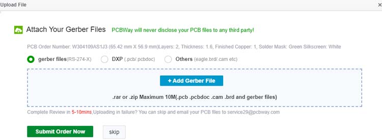
Step 3: The final step is to upload the Gerber file and proceed with the payment. To make sure the process is smooth, PCBWAY verifies if your Gerber file is valid before proceeding with the payment. This way, you can be sure that your PCB is fabrication friendly and will reach you as committed.
Assembling the PCB
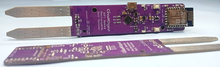
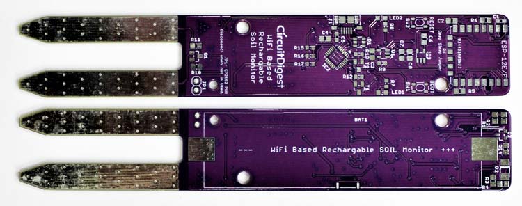
After the board was ordered, it reached to me after some days through courier in a neatly labeled well-packed box. The PCB quality was good as always. The top layer and the bottom layer of the board are shown below:
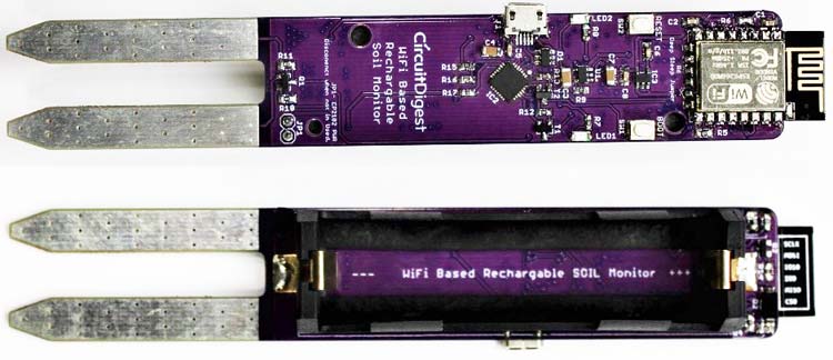
After making sure the tracks and footprints were correct. I proceeded with the assembling of the PCB. The completely soldered board looks like the below:

Adafruit IO Setup
Adafruit IO is an open data platform that allows you to aggregate, visualize, and analyze live data on the cloud. Using Adafruit IO, you can upload, display, and monitor your data over the internet, and make your project IoT-enabled. You can control motors, read sensor data, and make cool IoT applications over the internet using Adafruit IO.
To use Adafruit IO, first, you have to create an account on Adafruit IO. To do this, go to the Adafruit IO website and click on ‘Get started for Free’ on the top right of the screen.

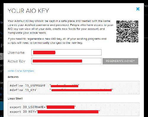
After finishing the account creation process, log in to your account and click on ‘View AIO Key’ on the top right corner to get your account username and AIO key.
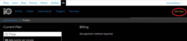
When you click on ‘AIO Key,’ a window will pop up with your Adafruit IO AIO Key and username. Copy this key and username. You'll need it later in your code.
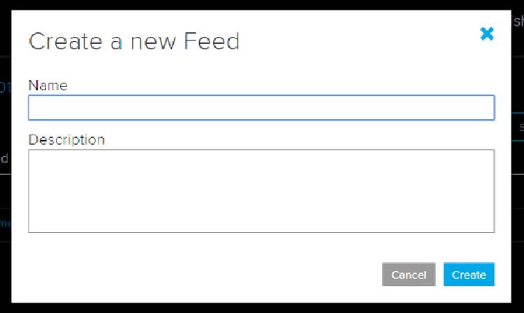
Now, after this, you need to create a feed. To create a feed, click on ‘Feed.’ Then click on ‘Actions,’ you will see some options, from them, click on ‘Create a New Feed.’

After this, a new window will open where you need to input the Name and Description of your feed. Writing a description is optional. Click on ‘Create’, and you will be redirected to the newly created feed.
After creating the feed, now we will create an Adafruit IO dashboard to plot these readings in a graph.
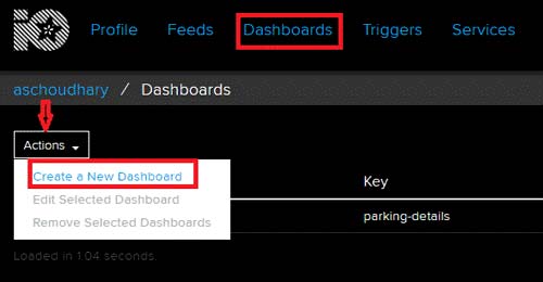
To create a dashboard, click on the Dashboard option and then click on the ‘Action,’ and after this, click on ‘Create a New Dashboard.’ In the next window, enter the name for your dashboard and click on ‘Create.’
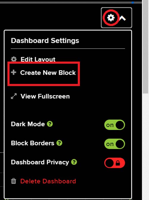
With this the dashboard is created, now we will add the ‘Line Chart’ block to the dashboard. To add a Block, click on the ‘Gear’ in the top right corner and then click on ‘Create New Block’. Then in the next window select the Line Chart block and the Feed from which you want to display the data.
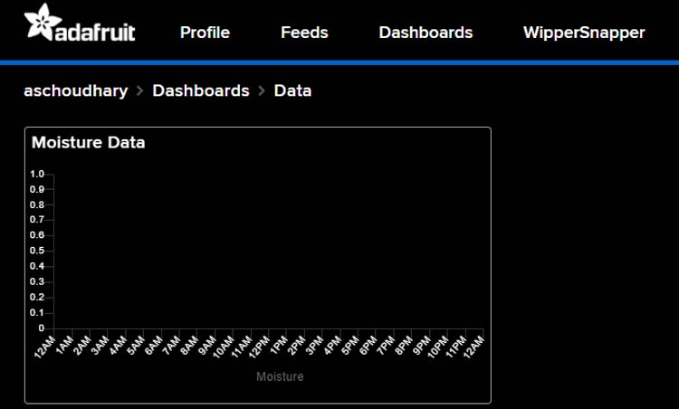
The final dashboard will look like this:
Programming the ESP-12E
The complete code for Smart Plant Monitoring Device is given at the end of the document. Here we are explaining some important parts of the code. The code uses the Adafruit_MQTT, and ESP8266WiFi.h libraries. The Adafruit_MQTT.h can be downloaded from the given link, and the ESP8266WiFi.h library comes pre-installed with the ESP board package.
After installing the libraries to Arduino IDE, start the code by including the required libraries files.
#include <ESP8266WiFi.h>
#include “Adafruit_MQTT.h”
#include “Adafruit_MQTT_Client.h”
Then in the next lines enter the Wi-Fi and Adafruit IO credentials that you copied from the Adafruit IO server. These will include the MQTT server, Port No, User Name, and AIO Key.
Const char *ssid =  “Wi-Fi Name”;
const char *pass =  “Password”;
#define MQTT_SERV “io.adafruit.com”
#define MQTT_PORT 1883
#define MQTT_NAME “Usernae”
#define MQTT_PASS “Password”
Adafruit MQTT can be used for two things. You can publish data to the broker, and you can subscribe to data from the broker. Here we are going to publish the data to the broker. For that first, we have to create an Adafruit_MQTT_Client mqtt() object and then set up the Adafruit IO feed for storing the sensor data.
Adafruit_MQTT_Client mqtt(&client, MQTT_SERV, MQTT_PORT, MQTT_NAME, MQTT_PASS); Adafruit_MQTT_Publish Moisture = Adafruit_MQTT_Publish(&mqtt,MQTT_NAME “/f/Moisture”);
Inside the moisture() function we are first reading the moisture data from the soil moisture sensor that is connected to the A0 pin of ESP. Then these readings are converted to percentage and in the last the data is published to the Adafruit IO feed.
Void moisture() {
  MQTT_connect();
  moisturePercentage = ( 100.00 – ( (analogRead(moisturePin) / 1023.00) * 100.00 ) );
  Serial.println(“Soil Moisture is  = “);
  Serial.println(moisturePercentage);
  Serial.println(“%”);
  delay(900);
  Moisture.publish(moisturePercentage);
}
Now comes the void loop(). This is where all the tasks are performed. In this loop, first, we are calling the moisture() function to get the sensor data and to publish it on Adafruit IO. Finally, the important function to call is ESP.deepSleep(). This will make the module sleep for the defined interval of time which is 1 hour in this case.
Void loop() {
  moisture();
  delay(3000);
  Serial.println(“deep sleep for 1 hour”);
  ESP.deepSleep(3600e6);
}
Testing the Smart Plant Monitoring Device
Now, everything is done, the last step is to put this device inside a plant pot and see how everything works. But before that let's first upload the code on ESP-12E. For that connect the USB cable to the micro-USB port of the device, and select ‘Generic ESP8266 Module’ as Board. Then select the port number and hit the upload button.
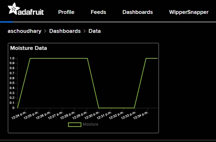
The device is programmed to read the sensor data, publish it on Adafruit IO, and then it will go to Deep Sleep mode for 1 hour. The soil moisture readings will be displayed on Adafruit IO:
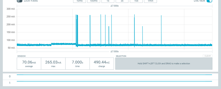
To calculate the Battery run time, we measured the current consumption in normal mode and deep sleep mode using the Nordic Power Profiler Kit II. Current consumption in Normal mode was 70mA as shown in the below graph:
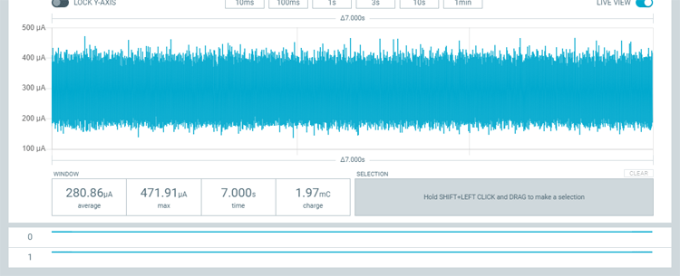
And current consumption in deep sleep mode was 280 µA on average:
We used these readings to calculate the battery run time. The calculations are as below:
In wake mode we have 70 mA for 10 to 12 seconds every 1 hour = 12 * 24 = 288 seconds. That is around 5 mins. The rest of the time that is 23-hour 55 minutes, the device will be in sleep mode.
So, the total current consumption will be:
Total Current Consumption = Current consumption in Wake Mode + Current Consumption in Sleep mode
Ttotal = 0.005A + 0.00669A = 0.01169 Battery Run Time = Battery Capacity (2600mAh) / Current Consumption (0.01169A)= 2.6 Ah/ 0.01169 = 222 Days
These calculations are done roughly but it gives an estimation about battery run time. That’s all, a complete video with a detailed explanation about circuit, code, and working is given below. If you have any questions, please put them in the comment section or you use our forum to start a discussion on it.
Complete Project Code
#include <ESP8266WiFi.h>
#include "Adafruit_MQTT.h"
#include "Adafruit_MQTT_Client.h"
const int moisturePin = A0;  // moisteure sensor pin
const int probe1 = 5;
const int probe2 = 4;
float moisturePercentage;              //moisture reading
const char *ssid =  "Galaxy-M20";     // Enter your WiFi Name
const char *pass =  "ac312124"; // Enter your WiFi Password
WiFiClient client;
#define MQTT_SERV "io.adafruit.com"
#define MQTT_PORT 1883
#define MQTT_NAME "aschoudhary" // Your Adafruit IO Username
#define MQTT_PASS "1ac95cb8580b4271bbb6d9f75d0668f1" // Adafruit IO AIO key
Adafruit_MQTT_Client mqtt(&client, MQTT_SERV, MQTT_PORT, MQTT_NAME, MQTT_PASS);
Adafruit_MQTT_Publish Moisture = Adafruit_MQTT_Publish(&mqtt,MQTT_NAME "/f/Moisture");  // Moisture is the feed name where you will publish your data
const unsigned long Interval = 50000;
unsigned long previousTime = 0;
void setup()
{
  Serial.begin(9600);
  delay(10);
  pinMode(probe1, OUTPUT);
  pinMode(probe2, OUTPUT);
  digitalWrite(probe1, HIGH);
  digitalWrite(probe2, HIGH);
  Serial.println("Connecting to ");
  Serial.println(ssid);
  WiFi.begin(ssid, pass);
  while (WiFi.status() != WL_CONNECTED)
  {
    delay(500);
    Serial.print(".");              // print ... till not connected
  }
  Serial.println("");
  Serial.println("WiFi connected");
}
void moisture()
{
  MQTT_connect();
  moisturePercentage = ( 100.00 - ( (analogRead(moisturePin) / 1023.00) * 100.00 ) );
  Serial.println("Soil Moisture is  = ");
  Serial.println(moisturePercentage);
  Serial.println("%");
  delay(900);
  Moisture.publish(moisturePercentage);
}
void loop()
{
  moisture();
  delay(3000);
  Serial.println("deep sleep for 1 hour");
  ESP.deepSleep(3600e6);
}
void MQTT_connect()
{
  int8_t ret;
  // Stop if already connected.
  if (mqtt.connected())
  {
    return;
  }
  uint8_t retries = 3;
  while ((ret = mqtt.connect()) != 0) // connect will return 0 for connected
  {
       mqtt.disconnect();
       delay(5000);  // wait 5 seconds
       retries--;
       if (retries == 0)
       {
         // basically die and wait for WDT to reset me
         while (1);
       }
  }
}
Comments
Thankyou for this article…
Thankyou for this article regarding IoT based soil moisture monitoring device. Smart IoT Farming is almost impossible without it.

Un reconocimiento por la publicación de desarrollos que son de beneficio para el medio ambiente y para la comunidad dedicada a la electronica. Bravo