
A digital pulse oximeter and heart rate sensor is an electronic device which can measure the heart rate of a person by measuring the difference between oxygen rich and oxygen less blood. Not only heart rate, this device can also measure the concentration of oxygen in blood. So in this article, we will interface the popular MAX30102 pulse oximeter and heart rate sensor with Arduino and in the process learn how this sensor works. So without further ado let's get right into it.
The MAX30102 Pulse Oximeter and Heart Rate Sensor
The MAX30102 is a very versatile sensor and it can also measure body temperature other than heart rate and blood oxygen level. This is a sensor designed by Analog Devices and features two LEDs (one Infrared and one Red), a photodetector, optics, and low-noise signal processing unit to detect pulse oximetry (SpO2) and heart rate (HR) signals.
The main idea is that you shine a single LED at a time and check the amount of light that is getting reflected back to the sensor. Based on the reflection you can determine the blood oxygen level and heart rate. This is a very short explanation of how this sensor works and we will elaborate more later in the article. But for now, let's check other parameters of the sensor
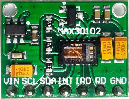
MAX30102 Pulse Oximeter and Heart Rate Sensor Pinout
The MAX30102 Digital Pulse Oximeter and Heart Rate Sensor, and this module have 7 pins VCC, SCL, SDA, INT, IRD, RD, and GND. All the pins of this sensor module are digital, except VCC and Ground. The Pinout of the Pulse Oximeter and Heart Rate Sensor is shown below:
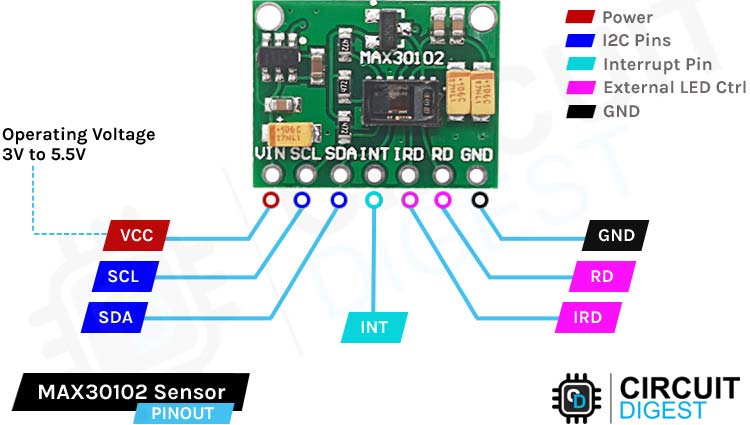
VCC is the power supply pin of the Pulse Oximeter and Heart Rate Sensor that can be connected to 3.3V or 5V of the supply.
SCL SCL stands for Serial Clock the master device pulses this pin at a regular interval to generate clock signal for communication. Connect to the A5 pin of the Arduino.
SDA Stands for Serial Data, through this pin data exchange happens between two devices. Connect this pin to the A4 pin of the Arduino.
INT is the Interrupt pin of the IC. This IC can be programmed to generate an Interrupt a on each pulse. This pin is open drain in nature, so it's pulled high through an onboard resistor. When there is an interrupt this pin goes low and stays low until the interrupt is cleared.
IRD This is the pin that is connected to the IR LED of the Module. This module has a LED driver built in. use this pin if you want to manually drive the LED with code, otherwise leave the pin open.
RD this pin is similar to the IRD pin the only difference is that a RED LED is connected to this pin. Leave it untouched if you don't want to drive the LED yourself.
GND is the ground pin of the pulse Oximeter and Heart Rate Sensor module and it should be connected to the ground pin of the Arduino.
Operating Power of MAX30102 Pulse Oximeter and Heart Rate Sensor
The operating voltage of the module is 3.3V to 5V with 600uA of Maximum current draw. But If we are talking about the MAX30102 IC on the module board the IC requires two different supply voltages for stable operation, which is why in the module board you can find two linear low dropout regulators. One is for 3.3V and the other one is for 1.8V. You can check out the parts marking section for better understanding. One of the most interesting features of this module is its power consumption, MAX30102 consumes less than 600μA during measurement. And it consumes only 0.7μA when it's in standby mode.
Because of this low power consumption, this device can be used in battery powered applications. Other than that this IC offers a I2C Interface for communication, a FIFO buffer for holding and sampling 16 different readings, and an ON-Chip Temperature Sensor to measure the body temperature.
Interrupts on MAX30102 Pulse Oximeter and Heart Rate Sensor:
According to the datasheet of the MAX30102 Sensor, it offers 5 different types of interrupts. These interrupts can be used to perform other tasks in the microcontroller while the sensor is collecting data. Those are shown down below.
Power Ready: On power-up or after a brownout condition, when the supply voltage VDD transitions from below the UVLO voltage to above the UVLO voltage, a power-ready interrupt is triggered to signal that the IC is powered up and ready to collect data
SPO2 Data Ready: In SpO2 mode, this interrupt triggers after every data sample is collected. A SpO2 data sample consists of one IR and one red data point. This bit is automatically cleared when the FIFO data register is read.
Heart Rate Data Ready: In heart rate or SPO2 mode, this interrupt triggers after every data sample is collected. A heart rate data sample consists of one IR data point only. This bit is automatically cleared when the FIFO data register is read.
Temperature Ready: When an internal die temperature conversion is finished, this interrupt is triggered.
FIFO Almost Full: In SpO2 and heart-rate modes, this interrupt triggers when the FIFO write pointer is the same as the FIFO read pointer minus one, which means that the FIFO has only one unwritten space left. If the FIFO is not read within the next conversion time, the FIFO becomes full and future data is lost.
The INT line is an open drain, so it is pulled HIGH by the onboard resistor. When an interrupt occurs the INT pin goes LOW and stays LOW until the interrupt is cleared.
How does the MAX30102 Pulse Oximeter and Heart Rate Sensor Works?
As we have discussed earlier the max30102 sensor consists of a Red LED and an IR LED and a photodetector respectively. The wavelength of the RED Led is 660 nm and the wavelength of the IR Led is 880nm.
The MAX30102 Sensor shines both the light through the skin and measures the reflection with the photodetector. This method of pulse detection through light is called Photoplethysmogram. The working of the sensor can be divided into two parts one is heart rate measurement and another is blood oxygen level measurement.
The oxygen in the hemoglobin has a specific characteristic, that it can absorb IR light. When the concentration of hemoglobin is more, the redder the blood. Which simply means it can absorve more IR light. As the blood is pumped through the veins in the finger the amount of reflected light changes creating an oscillating waveform. And by measuring this wave we can get the heartbeat reading. Blood oxygen level measurement works on the principle that Red and IR light varies depending upon the oxygen level in your blood. Deoxygenated blood absorbs more RED light while blood with more sufficient oxygen absorbs more IR light. By measuring the ratio between two we can measure oxygen level.
MAX30102 Pulse Oximeter and Heart Rate Sensor Module – Parts
The manufacturer made this sensor so that anybody with basic knowledge in electronics can work with this sensor, so it requires very few readily available parts like three resistors and two filter capacitors, and two LDOs for stable operation. The parts marking of the sensor is shown below.
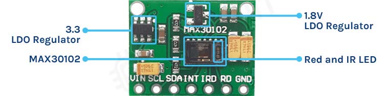
This sensor has seven pins altogether, among those two are power pins which are VCC and GND. And the other five pins are for data and clock signals which are 3.3V tolerant. As you can see the board has a handful of filter capacitors. As you can see in the above image the board has a couple of filter capacitors for two LDOs and 3 resistors for SCL, SDA and INT line. But there is a problem with the module, and we will discuss that later in the article.
Commonly Asked Questions about MAX30102 Pulse Oximeter and Heart Rate Sensor Module
How accurate is MAX30102?
A study conducted by IJEECS suggests that the accuracy rate of the MAX30102 measurement is 97.11% and 98.84%, for heart rate and oxygen saturation (SpO2), respectively. Bland Altman was used to appraising and visualizing the agreement between the two measurement devices.
Is MAX30102 FDA approved?
The chip acts as an integrated pulse oximetry and heart-rate monitor sensor solution. It should be noted that the MAX30102 is not an FDA-approved medical device and it's recommended to use for only small-scale projects.
What is a SpO2 sensor?
Pulse oximeters, also called SpO2 sensors, are used to measure blood oxygen levels or oxygen saturation in your blood. In the medical field, pulse oximeters are usually small devices that resemble a clip.

Circuit Diagram for MAX30102 Pulse Oximeter and Heart Rate Sensor Module
The schematic diagram of MAX30102 Pulse Oximeter and Heart Rate Sensor Module is shown below. The schematic itself is very simple and needs a handful of generic components to build. If you are implementing the circuit in a custom PCB this schematic will come in handy.
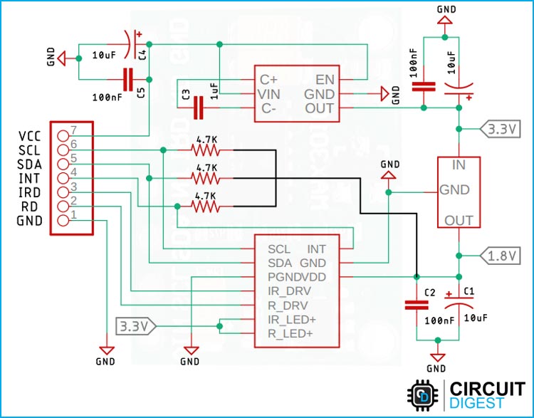
In the schematic, we have our MAX30102 and three pull-up resistors. Other than that we have two LDOs, the first one is for 3.3V and the second one is for 1.8V. The 1.8V supply is required to drive the sensor IC and the 3.3V is needed to drive the LEDs inside the IC. Other than that we have some filter capacitors and some decoupling capacitors that are required for stable operation for the LDOs. all these components make up the MAX30102 Sensor module.
Note: Please note that the schematic and the module has a major flaw in it that is why we made a portion of the schematic with black wires. We have discussed the problems and the solution in detail in the troubleshooting section of the article.
MAX30102 Pulse Oximeter and Heart Rate Sensor not Working? - Here is what you should do
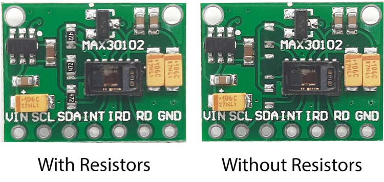
While working with the sensor module we have found two problems, the first one is mentioned in the schematic portion, as you can see in the schematic there are three pullup resistors on the module board but they are connected to 1.8V logic level and not 3.3V logic level. And now if we try to connect it to an arduino it will not work because the logic level is too low for Arduino. To solve this issue you need to remove those three pullup resistors and connect external resistors to the board. In the connection diagram section you can see how we did that.
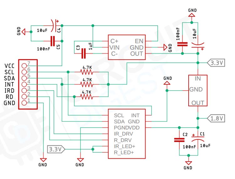
And in the above image we have made the necessary rectification to the schematic and you can use it as a reference without any issues. And you can also see the below image of the module with the resistor and without the resistors.
Difference between MAX30100 and MAX30102
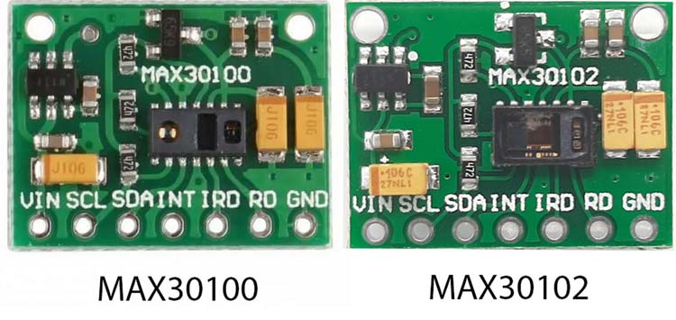
Second problem we found while using this sensor is that there are two different variants of this sensor one is MAX30100 and the other one is MAX30102. The specification and working of the two sensors are exactly the same but the arduino MAX30102 library required to communicate with those are totally different so make sure you are using the right module with the right library. In the image below you can see bothe the modules both look exactly the same but they are different in nature.
Third problem we found while working with the sensor is that this module needs a very strong pullup resistor for working. We tested the sensor with 10K pullup, 8.2K pullup, 4.7K pullup, and 3.3K pullup. Both 4.7K and 3.3K works but 10K and 8.2k does not work so we need to be careful with it.
Max30102 SPO2 Calculation
The calculation of SpO2, or blood oxygen saturation, using devices like the MAX30102 involves a method known as photoplethysmography (PPG), which is a non-invasive technique that uses a light-based technology to sense the volume of blood in a peripheral part of the body, such as a fingertip. Here’s a detailed explanation of how SpO2 is calculated:
The MAX30102 sensor employs two LEDs, one emitting red light (around 660 nm) and the other emitting infrared light (around 940 nm). The sensor also includes a photodetector that captures the light transmitted through the blood in the fingertip. The key principle behind SpO2 measurement is that oxygenated Hemoglobin (HbO2) and deoxygenated hemoglobin (Hb) absorb light differently at these two wavelengths.
Oxygenated hemoglobin (HbO2) absorbs less red light and more infrared light.
Deoxygenated hemoglobin (Hb) absorbs more red light and less infrared light.
The sensor alternately emits light from the red and infrared LEDs, which then passes through the finger and reaches the photodetector. The amount of light that passes through the finger varies with the pulsing of blood due to the heartbeat. This variation in light intensity is converted into a digital signal representing the absorption of light at each wavelength.
The device calculates the absorbance of light at both wavelengths. This is typically done by measuring the changes in light absorption during the pulse peaks and troughs. The absorbance is influenced by the arterial blood, as it changes volume with each heartbeat, while the absorbance by other tissues (venous blood, skin, bone, muscle) remains relatively constant.
The core of the SpO2 calculation is the ratio of ratios. This method involves forming a ratio of the red light measurement to the infrared light measurement for both the systolic (peak) and diastolic (trough) phases of the heartbeat. The formula is generally represented as:
R = (AC component of Red light / DC component of Red light) / (AC component of Red light / DC component of Red light)
Here, AC refers to the pulsatile component (varying with heartbeat), and DC refers to the non-pulsatile component (constant).
The calculated ratio (R) is then used in an empirical formula derived from calibration with a pulse oximeter that has been medically approved. This formula correlates the ratio (R) with SpO2 values, which is typically of the form:
SPO2 = A-B x R
Where A and B are coefficients determined through calibration. The exact relationship can vary depending on the specifics of the sensor and the manufacturer’s calibration.
Arduino MAX30102 Sensor Circuit Diagram
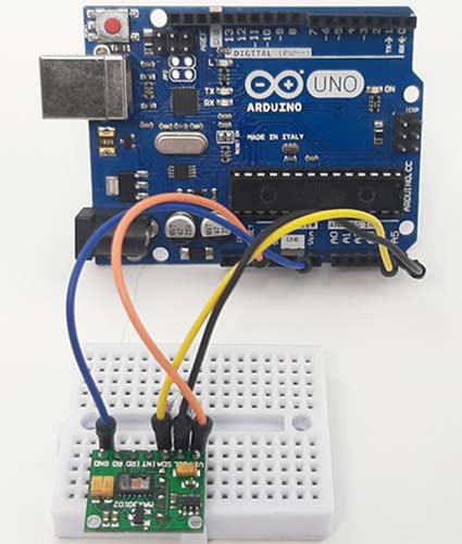
Now that we have a complete understanding of how a MAX30102 Pulse Oximeter and Heart Rate Sensor works, we can connect all the required wires to Arduino and then write our code to get the data out of the sensor module. The MAX30102 Arduino Connection Diagram is given below

Connecting the MAX30102 Pulse Oximeterto the microcontroller is really simple. As we all know, to communicate with the sensor we need to connect the I2C line which are A5 and A4 of the Arduino board to the sensor board. We also need to connect the INT or Interrupt pin of the sensor to D2 of the Arduino. At last we need to connect the VCC and ground pins to the 3.3V pin and Ground pin of the Arduino. A hardwear image of the setup is shown below.
Arduino MAX30102 Sensor Code
The code to acquire data from MAX30102 Sensor is very simple and easy to understand. We just need to include the required libraries for the Arduino and we can load up the example sketch for that. If everything is connected correctly, we can see the output data on the serial monitor window, but let's just not take the easy way and try to understand how the code works.
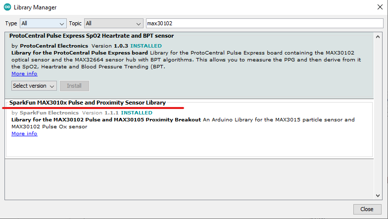
Before that, we need to install the required library. As we are using the MAX30102 module we need to install the SparkFun MAX3010X Pulse and Proximity Sensor Library from Arduino Library Manager.
We initialize our code by including all the required libraries and we also make an instance of the MAX30105 class named particleSensor.
Next, we will be defining some variables that will hold IR data and LED data. This is done because we need to do some sampling for stable results.
#include <Wire.h>
#include "MAX30105.h"
#include "heartRate.h"
MAX30105 particleSensor;
Next we define some variables that are required to store the heart beat result and for averaging the received values.
const byte RATE_SIZE = 4; //Increase this for more averaging. 4 is good.
byte rates[RATE_SIZE]; //Array of heart rates
byte rateSpot = 0;
long lastBeat = 0; //Time at which the last beat occurred
float beatsPerMinute;
int beatAvg;
Next, we have our setup function. In the setup function we initialize the serial and check if we can establish communication with the sensor or not. If it's false we will print the serial monitor window. If we get a true result we will continue with the code and set the RED led to low so that we can understand the sensor is working.
void setup()
{
  Serial.begin(115200);
  Serial.println("Initializing...");
  // Initialize sensor
  if (!particleSensor.begin(Wire, I2C_SPEED_FAST)) //Use default I2C port, 400kHz speed
  {
    Serial.println("MAX30105 was not found. Please check wiring/power. ");
    while (1);
  }
  Serial.println("Place your index finger on the sensor with steady pressure.");
  particleSensor.setup(); //Configure sensor with default settings
  particleSensor.setPulseAmplitudeRed(0x0A); //Turn Red LED to low to indicate sensor is running
  particleSensor.setPulseAmplitudeGreen(0); //Turn off Green LED
}
Next, we have our loop function, in the loop function we will declare a long variable named irValue and we will store all the data coming from the sensor in this variable, with the data stored in the variable, we can compute the heart rate with some proper calculation recommended by the datasheet.
{
  long irValue = particleSensor.getIR();
  if (checkForBeat(i rValue) == true) // checkForBeat is a function of heartRate.h Library
  {
    //We sensed a beat!
    long delta = millis() - lastBeat;
    lastBeat = millis();
    beatsPerMinute = 60 / (delta / 1000.0);
    if (beatsPerMinute < 255 && beatsPerMinute > 20)
    {
      rates[rateSpot++] = (byte)beatsPerMinute; //Store this reading in the array
      rateSpot %= RATE_SIZE; //Wrap variable
      //Take average of readings
      beatAvg = 0;
      for (byte x = 0 ; x < RATE_SIZE ; x++)
        beatAvg += rates[x];
      beatAvg /= RATE_SIZE;
    }
  }
  Serial.print("IR=");
  Serial.print(irValue);
  Serial.print(", BPM=");
  Serial.print(beatsPerMinute);
  Serial.print(", Avg BPM=");
  Serial.print(beatAvg);
  if (irValue < 50000)
    Serial.print(" No finger?");
  Serial.println();
}
This is the end of our code section. And we can move to the next section of this article.
Working of the MAX30102 Pulse Oximeter and Heart Rate Sensor
The gif below shows the hardware circuitry of the MAX30102 sensor with arduino in action. On the left-hand side, we have placed the Arduino with the MAX30102 sensor connected to the the SCL and SDA pin of the arduino and on the right hand side we have the serial monitor window and as you can see the when we place a finger on top of the sensor you can get the heart rate and SPO2 measurement on the serial monitor window.
GitHub Code and Circuit
The GitHub Repository below is linked with this MAX30102 Arduino tutorial, it consists of the MAX30102 Arduino Connection diagram and also an example code for you to try out this tutorial.


Projects using Arduino Pulse Oximeter and Heart Rate Sensor Module

If you are interested in building your own arduino based compact pulse oximeter circuit this project could be for you. Because in this project also we have shown you how you can use the MAX30102 sensor with an arduino and display the data onto an OLED display.

If you are interested in building an IoT based Pulse Oximeter and heart rate monitor system you can check this project out. In this project we have used the populer ESP32 microcontroller and a MAX30102 Pulse Oximeter and Heart Rate Sensor module to do just that.

If you are interested in building projects with PIC microcontrollers and searching the internet for some interesting projects, this project could be for you. Because in this project we have interfaced a LCD and a generic heart rate sensor to build yourself a DIY! Heart rate monitoring system.
Complete Project Code
/*
  Optical Heart Rate Detection (PBA Algorithm) using the MAX30105 Breakout
  By: Nathan Seidle @ SparkFun Electronics
  Date: October 2nd, 2016
  https://github.com/sparkfun/MAX30105_Breakout
  This is a demo to show the reading of heart rate or beats per minute (BPM) using
  a Penpheral Beat Amplitude (PBA) algorithm.
  It is best to attach the sensor to your finger using a rubber band or other tightening
  device. Humans are generally bad at applying constant pressure to a thing. When you
  press your finger against the sensor it varies enough to cause the blood in your
  finger to flow differently which causes the sensor readings to go wonky.
  Hardware Connections (Breakoutboard to Arduino):
  -5V = 5V (3.3V is allowed)
  -GND = GND
  -SDA = A4 (or SDA)
  -SCL = A5 (or SCL)
  -INT = Not connected
  The MAX30105 Breakout can handle 5V or 3.3V I2C logic. We recommend powering the board with 5V
  but it will also run at 3.3V.
*/
#include <Wire.h>
#include "MAX30105.h"
#include "heartRate.h"
MAX30105 particleSensor;
const byte RATE_SIZE = 4; //Increase this for more averaging. 4 is good.
byte rates[RATE_SIZE]; //Array of heart rates
byte rateSpot = 0;
long lastBeat = 0; //Time at which the last beat occurred
float beatsPerMinute;
int beatAvg;
void setup()
{
  Serial.begin(115200);
  Serial.println("Initializing...");
  // Initialize sensor
  if (!particleSensor.begin(Wire, I2C_SPEED_FAST)) //Use default I2C port, 400kHz speed
  {
    Serial.println("MAX30105 was not found. Please check wiring/power. ");
    while (1);
  }
  Serial.println("Place your index finger on the sensor with steady pressure.");
  particleSensor.setup(); //Configure sensor with default settings
  particleSensor.setPulseAmplitudeRed(0x0A); //Turn Red LED to low to indicate sensor is running
  particleSensor.setPulseAmplitudeGreen(0); //Turn off Green LED
}
void loop()
{
  long irValue = particleSensor.getIR();
  if (checkForBeat(irValue) == true)
  {
    //We sensed a beat!
    long delta = millis() - lastBeat;
    lastBeat = millis();
    beatsPerMinute = 60 / (delta / 1000.0);
    if (beatsPerMinute < 255 && beatsPerMinute > 20)
    {
      rates[rateSpot++] = (byte)beatsPerMinute; //Store this reading in the array
      rateSpot %= RATE_SIZE; //Wrap variable
      //Take average of readings
      beatAvg = 0;
      for (byte x = 0 ; x < RATE_SIZE ; x++)
        beatAvg += rates[x];
      beatAvg /= RATE_SIZE;
    }
  }
  Serial.print("IR=");
  Serial.print(irValue);
  Serial.print(", BPM=");
  Serial.print(beatsPerMinute);
  Serial.print(", Avg BPM=");
  Serial.print(beatAvg);
  if (irValue < 50000)
    Serial.print(" No finger?");
  Serial.println();
}
Hi! I tried using this code for my MAX30102. However, I did not manage to get it to run. I tried adding in some print statements and realised that after the "Initializing..." print, the serial monitor is stuck there, with no new prints of whether MAX30105 was found or not. I noticed that if my SCL and SDA is unplugged, it would then produce the print statement "MAX30105 was not found. Please check wiring/power."
May I check if anyone knows what is causing the issue?