

We are all aware of a basic voltmeter, ammeter, and wattmeters, the three basic things you need to measure values on any electronic projects or circuits. Measuring voltage and current with the help of a multimeter can be a good way to start, but one of the biggest problems I face while testing a circuit is, measuring power efficiency. So, today we will solve that problem by building an Arduino and ESP32 based efficiency meter that can measure input voltage, input current, output voltage, and output current. Hence, it can measure input power and output power at the same time, and with these values, we can measure efficiency easily. Previously, we have also done something very similar in our Arduino Based Wattmeter project, but here we will measure both input power and output power to calculate power efficiency.
Rather than purchasing four meters for the job, we will be able to solve this problem by incorporating the capabilities of all four meters into one. Building your digital meter not only reduces cost but also gives you a wiggle room for upgrades and improvements. As we are using an ESP32 to build this project, we can easily make this meter IoT enabled and log data over the web, which is the topic for the future project. With all the basics cleared out, let’s get right into it.
Note: This power meter is designed for DC circuits. If you are looking to measure AC current to calculated AC power efficiency you can check out the IoT based Electricity Energy Meter and Prepaid Energy Meter Projects.
Materials Required for ESP32 Power Meter
The image below shows the materials used to build the circuit. As this is made with very generic components, you should be able to find all of the listed material in your local hobby store.
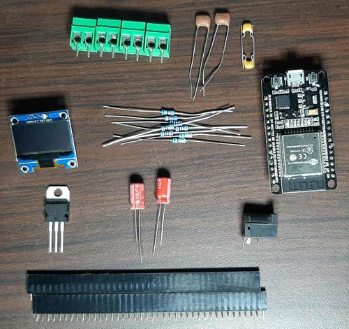
I have also listed the components below along with the required quantity. If you are building the circuit yourself, it's highly recommended to get all the materials from the list below.
- ESP32 Board - 1
- 128X64 OLED - 1
- ACS712-20 IC - 2
- DC Barrel Jack - 1
- 100uF Capacitor - 2
- 104pF - 2
- 102pF - 2
- 10K, 1% - 4
- 68K, 1% - 2
- 6.8K, 1% - 2
Arduino and ESP32 Based Efficiency Meter - Circuit Diagram
The schematic for the Arduino and ESP32 Based Efficiency Meter is shown below. Creating this circuit is very simple and uses generic components.

The operation of the circuit is very simple. We will be measuring the voltage and current in this project but in a unique way. We are measuring voltage and current for both the input and output, hence we can see the efficiency of the circuit. This comes in very handy for some projects. An example could be a DC to DC converter where efficiency measurement becomes mandatory. The way these circuit works is described below.
The ACS712 Current Sensor IC:
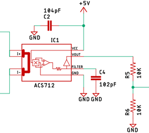
As you can see in the above picture, we are using an ACS712 Current Sensor IC to measure current. This is a very interesting IC as it uses the Hall-effect to measure current, there are three variants of this IC that can be found in the market f(or 5A, 20A, and 30A). We are using the 20A variant of this and it's labeled as ACS712-20.
The ACS712 datasheet recommends a voltage range of 4.5 - 5.5 to operate smoothly. And as we are going to measure the current with an ESP32, it's only 3.3V tolerant, which is why I have used a voltage divider with two 10K resistors to bring down the output voltage of the ACS712 IC. When no current is flowing through the IC, it outputs 2.5V, and when some amount of current flows through the IC, it either lowers the voltage or it increases the voltage depending on the current flow direction. We have used two of these ICs to measure input and output current. Check out our previous projects (below) in which we used this ACS712 Sensor.
- IoT Based Electricity Energy meter using Arduino and ESP8266 Wi-Fi module
- Digital Ammeter Circuit using PIC Microcontroller and ACS712
Where we discussed the working of these sensors in detail. You can check those out if you want to know more about these sensors.
The Voltage Divider:
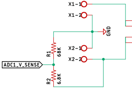
To measure the input and output voltage, we have two voltage dividers on the input and the output side of the circuit. The maximum voltage that the circuit can measure is 35V, but it can be easily changed by changing the resistor values for the voltage divider.
The Voltage Regulator:
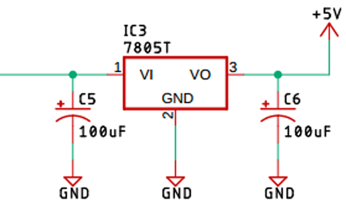
A generic LM7805 voltage regulator is used to power the ESP32, OLED, and ACS712 ICs. As we are powering it up with fairly clean power, no decoupling capacitors are used, but we have used 100uF capacitors at both the input and output to stabilize the IC.
The ESP32 IC and the OLED Display:
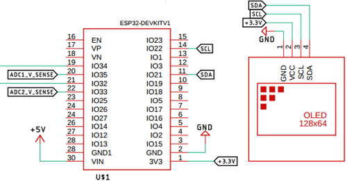
We have used an ESP32 as the main processor, which is responsible for all the readings, calculations, inputs, and outputs. Also, we have used a 128X64 OLED display to know the values.
PCB Design for Arduino and ESP32 Based Efficiency Meter
The PCB for our Arduino and ESP32 Based Efficiency Meter is designed on a single-sided board. I have used Eagle to design my PCB but you can use any design software of your choice. The 2D image of my board design is shown below.
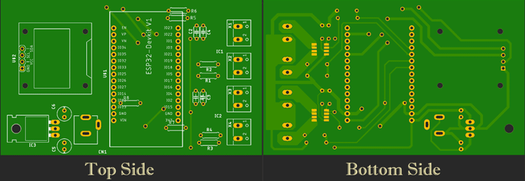
Sufficient ground trace is used to make proper ground connections among all the components. Also, we made sure to use proper 5V and 3.3V traces to reduce noise and improve efficiency.
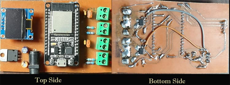
Handmade PCB:
For convenience and testing, I made my handmade version of the PCB and it's shown below. In the first version, I made some mistakes, which I rectified using some jumper wires. But in the final version, I fixed those, you can just download the files and use them.
Arduino and ESP32 Based Efficiency Meter - Code
Now, that we have a good understanding of the hardware side of things, we can open the Arduino IDE and start our coding. The purpose of the code is to read the analog voltage from pin 35 and 33 of the ESP32 board. Also, we read the voltage from 32, and 34 pin which is the current value. Once we do this, we can multiply those to get input power and output power, and putting it on to the efficiency formula, we can get the efficiency.
Finally, we display it on the LCD screen. The complete program to do the same is given at the end, which can be used as such for the hardware discussed above. Further, the code is split into small snippets and explained.
As we are using a 128X64 OLED display, we need the Adafruit_GFX library and the Adafruit_SSD1306 library to communicate with the display. You can download both of them from the Arduino’s default board manager terminal; if you are having any issues with the board manager part, you can also download and include the libraries from its associated GitHub repository, which is given below.
As always, we begin our code by including all the required libraries. Then we define all the necessary pins and variables all of which are shown below.
#include <Wire.h>
#include <Adafruit_GFX.h>
#include <Adafruit_SSD1306.h>
#include <math.h>
#define SCREEN_WIDTH 128 // OLED display width, in pixels
#define SCREEN_HEIGHT 64 // OLED display height, in pixels
#define INPUT_VOLTAGE_SENSE_PIN 33
#define OUTPUT_VOLTAGE_SENSE_PIN 35
#define INPUT_CURRENT_SENSE_PIN 32
#define OUTPUT_CURRENT_SENSE_PIN 34
double  R1_VOLTAGE = 68000; //68K
double  R2_VOLTAGE = 6800; // 6.8K
double  R1_Current 10000 //10K
double  R2_Current 22000 //22K
//We have used 50 as mVperp value; please refer to the documentation for further information
double mVperAmp = 50; // use 100 for 20A Module and 66 for 30A Module
double ACSoffset = /*1130*/ 1136;
// Declaration for an SSD1306 display connected to I2C (SDA, SCL pins)
Adafruit_SSD1306 display(SCREEN_WIDTH, SCREEN_HEIGHT, &Wire, -1);
The SCREEN_WIDTH & SCREEN_HEIGHT definitions are used to define the screen size. Next we have defined all the necessary pins, through which we are going to measure the voltage and current. Next, we have defined the resistor values which are used in the hardware as you can see from the schematic. If you don’t have these values or if you want to change the range of the meter, you can change those values, the code will work just fine.
As we are using an ACS712 to measure the current, we need the mVperAmp value to calculate the current from voltage. As I am using a 20A ACS712 module, the mV/A value is 100 as given in the datasheet. But because we are using an ESP32 and a voltage divider, we will have half the value which is 50, and that is why we have put in the mV/AMP value.
ACSoffset is the offset that is needed for calculating the current from the voltage. As the ACS712 IC’s are powered from 5V, the offset voltage is 2.5V. But as we are using a voltage divider, it goes down to 1.25V. You may already know the crappy ADC of the ESP32, so I had to use a value of 1136. If you are having calibration issues, you can tweak the values and compensate for the ADC.
Finally, we finish this section by making a display object of the Adafruit_SSD1306 class and passing the screen width, height, I2C configuration, and the last -1 parameter is used to define the reset functionality. If your display doesn’t have an external reset pin (which certainly is for my display), then you have to use -1 for the last argument.
void setup() {
  Serial.begin(115200);
  if (!display.begin(SSD1306_SWITCHCAPVCC, 0x3C)) { // Address 0x3D for 128x64
    Serial.println(F("SSD1306 allocation failed"));
    for (;;);
  }
  display.clearDisplay();
  display.setRotation(2);
  display.setTextSize(1);
  delay(100);
}
Next, we have our setup() section. In this section, we enable serial for debugging, we check if an I2C display is available or not with the help of the beginning method of the display object. Also, we set the I2C address. Next, we clear the display with the clearDisplay() method. Also, we rotate the display with the setRotation method, it's because I have messed up my PCB design. Next, we put a delay of 100 ms for the functions to take effect. Once that is done, we can now move on to the loop function. But before proceeding to the loop function, we need to discuss two other functions which are return_voltage_value(), and return_current_value().
double return_voltage_value(int pin_no)
{
  double tmp = 0;
  double ADCVoltage = 0;
  double inputVoltage = 0;
  double avg = 0;
  for (int i = 0; i < 150; i++)
  {
    tmp = tmp + analogRead(pin_no);
  }
  avg = tmp / 150;
  ADCVoltage = ((avg * 3.3) / (4095)) + 0.138;
  inputVoltage = ADCVoltage / (R2_VOLTAGE / (R1_VOLTAGE + R2_VOLTAGE)); // formula for calculating voltage in i.e. GND
  return inputVoltage;
}
The return_voltage_value() function is used to measure the voltage coming into the ADC, and it takes the pin_no as an argument. In this function, we start by declaring some variables, which are tmp, ADCVoltage, inputVoltage, and avg. The tmp variable is used to store the temporary ADC value which we get from the analogRead() function, then we average it out 150 times in a for loop, and we store the value to a variable called avg. We then calculate ADCVoltage from the given formula, finally, we calculate the input voltage and return the values. The +0.138 value you see is the calibration value I used to calibrate the voltage level, play around with this value if you are getting any errors.
double return_current_value(int pin_no)
{
  double tmp = 0;
  double avg = 0;
  double ADCVoltage = 0;
  double Amps = 0;
  for (int z = 0; z < 150; z++)
  {
    tmp = tmp + analogRead(pin_no);
  }
  avg = tmp / 150;
  ADCVoltage = ((avg / 4095.0) * 3300); // Gets you mV
  Amps = ((ADCVoltage - ACSoffset) / mVperAmp);
  return Amps;
}
Next, we have the return_current_value() function. This function also takes pin_no as argument. In this function also we have four variables viz. tmp, avg, ADCVoltage, and Amps
Next, we read the pin with analogRead() function and average it 150 times, next we use the formula to calculate the ADCvoltage, with that we calculate the current and we return the value. With that, we can move onto the loop section.
void loop()
{
  float input_voltage = abs(return_voltage_value(INPUT_VOLTAGE_SENSE_PIN)) ;
  float input_current = abs(return_current_value(INPUT_CURRENT_SENSE_PIN)) ;
  float output_voltage = abs(return_voltage_value(OUTPUT_VOLTAGE_SENSE_PIN)) ;
  float output_current =  abs((return_current_value(OUTPUT_CURRENT_SENSE_PIN))) ;
  input_current = input_current - 0.025;
  Serial.print("Input Voltage: ");
  Serial.print(input_voltage);
  Serial.print(" | Input Current: ");
  Serial.print(input_current);
  Serial.print(" | Output Voltage: ");
  Serial.print(output_voltage);
  Serial.print(" | Output Current: ");
  Serial.println(output_current);
  delay(300);
  display.clearDisplay();
  display.setCursor(0, 0);
  display.print("I/P V: ");
  display.setCursor(37, 0);
  display.print(input_voltage);
  display.setCursor(70, 0);
  display.print("V");
}
We start the loop section by declaring and defining some float variables, in all four variables. We call the respective functions, passing pin_no as an argument, as the ACS712 module can return current values in negative. We use the abs() function of the math library to make the negative value as positive. Next, we serial print all the values for debugging. Next, we clear the display, set the cursor, and print the values. We do this for all the characters shown in the display. Which marks the end of the loop function and the program.
Testing the Arduino and ESP32 Based Efficiency Meter
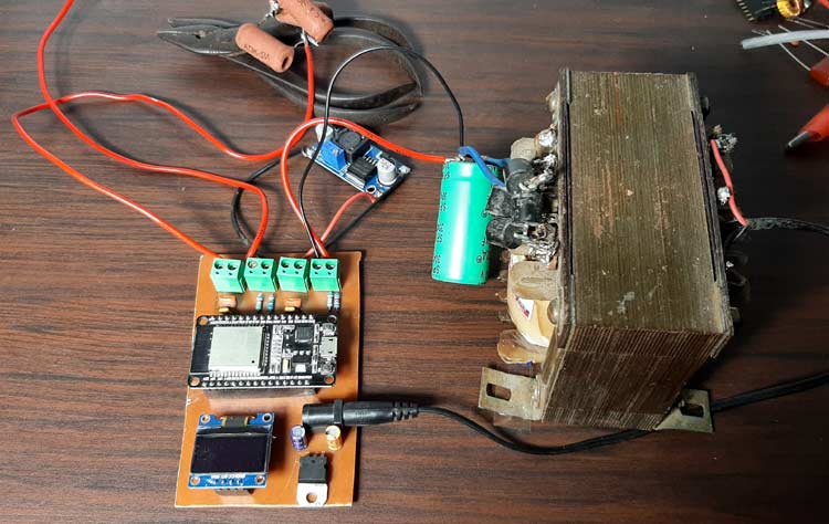
As you can see my test setup in the above image. I have my 30V transformer as input, and I have my meter hooked up for the test board. I am using an LM2596 based buck converter board and for the load and I am using three 10 Ohms resistors, in parallel.
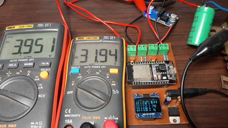
As you can see in the above image, I have connected to multi-meters to check the input and output voltage. The transformer produces almost 32V and the output of the buck converter is 3.95V.
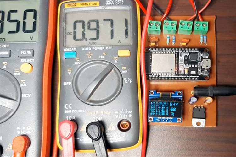
The image here shows the output current measured by my efficiency meter and the multimeter. As you can see, the multimeter shows .97 Amps, and if you zoom in a little bit, it shows 1.0A, it's slightly off due to non-linearity present in the ACS712 module but this serves our purpose. For a detailed explanation and testing, you can check out the video in our video section.

Further Enhancements
For this demonstration, the circuit is made on a handmade PCB but the circuit can be easily built in a good quality PCB. In my experiment, the size of the PCB is really big due to the component size, but in a production environment, it can be reduced by using cheap SMD components. The circuit also doesn't have any built-in protection feature, so including a protection circuit will improve the overall safety aspect of the circuit. Also, while writing the code, I noticed the ADC of the ESP32 is not that great. Including an external ADC like the ADS1115 module will increase the overall stability and accuracy.
I hope you liked this article and learned something new out of it. If you have any doubt, you can ask in the comments below or can use our forums for detailed discussion.
Complete Project Code
/*********
Arduino code for ESP32 based power meter to measure effeciancy
www.circuitdigest.com
*********/

#include <Wire.h>
#include <Adafruit_GFX.h>
#include <Adafruit_SSD1306.h>
#include <math.h>
#define SCREEN_WIDTH 128 // OLED display width, in pixels
#define SCREEN_HEIGHT 64 // OLED display height, in pixels
#define INPUT_VOLTAGE_SENSE_PIN 33
#define OUTPUT_VOLTAGE_SENSE_PIN 35
#define INPUT_CURRENT_SENSE_PIN 32
#define OUTPUT_CURRENT_SENSE_PIN 34
float  R1_VOLTAGE = 68000; //68K
float  R2_VOLTAGE = 6800; // 6.8K
#define R1_Current 10000 //10K
#define R2_Current 22000 //22K
//We have used 50 as mVperp value; please refer to the documentation for further information
double mVperAmp = 50; // use 100 for 20A Module and 66 for 30A Module
double ACSoffset = /*1130*/ 1136;
// Declaration for an SSD1306 display connected to I2C (SDA, SCL pins)
Adafruit_SSD1306 display(SCREEN_WIDTH, SCREEN_HEIGHT, &Wire, -1);
void setup() {
  Serial.begin(115200);
  if (!display.begin(SSD1306_SWITCHCAPVCC, 0x3C)) { // Address 0x3D for 128x64
    Serial.println(F("SSD1306 allocation failed"));
    for (;;);
  }
  delay(2000);
  display.clearDisplay();
  display.setRotation(2);
  display.setTextSize(1);
  display.setTextColor(WHITE);
  display.setCursor(0, 10);
  // Display static text
  display.println("Hello, world!");
  display.display();
  delay(100);
}
void loop()
{
  // Uncomment For Debugging
  //double a,b,c;
  //  a = analogRead(INPUT_CURRENT_SENSE_PIN);
  //  Serial.print("a: ");
  //  Serial.println(a);
  //  b = (a / 4095) * 3300;
  //  Serial.print("b: ");
  //  Serial.println(b);
  //  c = ((b - ACSoffset) / mVperAmp) ;
  //  Serial.print("c: ");
  //  Serial.println(c);
  //  Serial.print("Final: ");
  //  Serial.println(return_current_value(INPUT_CURRENT_SENSE_PIN));
  //  delay(700);
  float input_voltage = abs(return_voltage_value(INPUT_VOLTAGE_SENSE_PIN)) ;
  float input_current = abs(return_current_value(INPUT_CURRENT_SENSE_PIN)) ;
  float output_voltage = abs(return_voltage_value(OUTPUT_VOLTAGE_SENSE_PIN)) ;
  float output_current =  abs((return_current_value(OUTPUT_CURRENT_SENSE_PIN))) ;
  input_current = input_current - 0.025;
  Serial.print("Input Voltage: ");
  Serial.print(input_voltage);
  Serial.print(" | Input Current: ");
  Serial.print(input_current);
  Serial.print(" | Output Voltage: ");
  Serial.print(output_voltage);
  Serial.print(" | Output Current: ");
  Serial.println(output_current);
  delay(300);
  display.clearDisplay();
  display.setCursor(0, 0);
  display.print("I/P V: ");
  display.setCursor(37, 0);
  display.print(input_voltage);
  display.setCursor(70, 0);
  display.print("V");
  display.setCursor(0, 10);
  display.print("O/P V: ");
  display.setCursor(37, 10);
  display.print(output_voltage);
  display.setCursor(70, 10);
  display.print("V");
  display.setCursor(0, 20);
  display.print("I/P I: ");
  display.setCursor(37, 20);
  display.print(abs(input_current));
  display.setCursor(70, 20);
  display.print("A");
  display.setCursor(0, 30);
  display.print("O/P I: ");
  display.setCursor(37, 30);
  display.print(abs(output_current));
  display.setCursor(70, 30);
  display.print("A");
  display.setCursor(0, 40);
  display.print("I/P P: ");
  display.setCursor(37, 40);
  display.print(abs(input_current * input_voltage));
  display.setCursor(70, 40);
  display.print("W");
  display.setCursor(0, 50);
  display.print("O/P P: ");
  display.setCursor(37, 50);
  display.print(abs(output_current * output_voltage));
  display.setCursor(70, 50);
  display.print("W");
  display.setTextSize(2);
  display.setCursor(85, 0);
  display.print("Eff");
  display.setCursor(87, 23);
  display.print((abs((output_current * output_voltage) / (input_current * input_voltage)) * 100), 0);
  display.setCursor(92, 45);
  display.print("%");
  display.setTextSize(1);
  display.display();
  display.clearDisplay();
}
double return_voltage_value(int pin_no)
{
  double tmp = 0;
  double ADCVoltage = 0;
  double inputVoltage = 0;
  double avg = 0;
  for (int i = 0; i < 150; i++)
  {
    tmp = tmp + analogRead(pin_no);
  }
  avg = tmp / 150;
  ADCVoltage = ((avg * 3.3) / (4095)) + 0.138;
  inputVoltage = ADCVoltage / (R2_VOLTAGE / (R1_VOLTAGE + R2_VOLTAGE)); // formula for calculating voltage in i.e. GND
  return inputVoltage;
}
double return_current_value(int pin_no)
{
  double tmp = 0;
  double avg = 0;
  double ADCVoltage = 0;
  double Amps = 0;
  for (int z = 0; z < 150; z++)
  {
    tmp = tmp + analogRead(pin_no);
  }
  avg = tmp / 150;
  ADCVoltage = ((avg / 4095.0) * 3300); // Gets you mV
  Amps = ((ADCVoltage - ACSoffset) / mVperAmp);
  return Amps;
}
Hello can you send the more detailed electrical circuit as well as the steps to follow for the assembly please.