

Often times, we need to control bass, treble, and volume of our audio signal before passing it through amplification stages to prevent sound distortion. The circuit that amplifies the audio signal before it enters the main speaker amplifier is called an Audio Preamplifier. The use of an audio pre-amplifier ensures good audio quality and provides options to modify our sound system by using this as a primary audio circuit/device before feeding the audio signal to your amplifier/subwoofer/home theatre system. Also, we can control bass and treble for different songs and get a wide range of control over our audio system. This type of circuit that provides Bass and Treble control is also known as a BT Circuit Board. We have previously built a simple Mono Audio pre-amplifier using transistor, in this article, we will build a stereo pre-amplifier circuit with bass and treble control.
A pre-amplifier circuit can be designed using a Transistor or an Op-Amp IC, both designs have certain advantages and disadvantages although both practically work fine and improve sound quality. In this article, we will build a transistor-based pre-amplifier and check out it's working.
Component Required for Pre-Amplifier Circuit
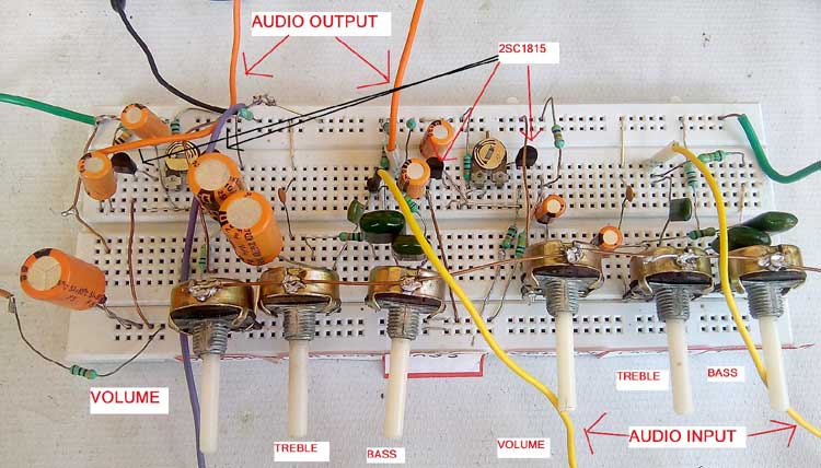
Our Stereo Pre-amplifier will have dual channels. The volume, bass, and treble of each channel can be controlled independently using potentiometers; hence it might look like a lot of components on the breadboard but they are all simple components and should be easily available. The list of materials required for the audio preamplifier circuit is given below.
| Component name | Value | Quantity |
| Potentiometer | 47k | 6 |
| Capacitor | 103 pf | 4 |
| Capacitor | 104 pf | 2 |
| Capacitor | 222 pf | 2 |
| Capacitor | 10uF/25V | 4 |
| Capacitor | 47uF/25V | 4 |
| Capacitor | 1000uF/25V | 1 |
| Resistor | 15k | 2 |
| Resistor | 10k | 6 |
| Resistor | 1k | 4 |
| Resistor | 560k | 2 |
| Resistor | 47k | 2 |
| Resistor | 2.7k | 2 |
| Resistor | 100 ohm | 1 |
| Variable Resistor(pot) | 2k | 2 |
| Zener Diode | 12V (IN4742A) | 1 |
| Transistor | 2sc1815 or C1815 | 4 |
Transistor-Based Dual Channel Stereo BT Circuit Diagram
The complete circuit diagram for Dual Channel Pre-Amplifier consists of two mono circuits combined to form one stereo circuit as shown in the image below. As you can see the left channel audio, and right channel audio feeds through two parts of the circuit and I have used 3 pieces of single-channel 47k potentiometers for controlling volume, bass, and treble. The audio source from the 3.5mm jack is given as input through a 15k resistor for the (Bass) potentiometer and on another pin of potentiometer grounded through 1k resistor for low frequency. For the treble (high frequency), the sound signal passes through 222 PF (polyester capacitor) to 47k potentiometer and grounded through 103pf and 10 uF capacitor for the volume potentiometer.

The main component of this circuit is the 2SC1815 transistor, which is a general-purpose NPN transistor that is commonly used for audio amplification and made for audio frequency driving pre-stage amplifier. The 2SC1815 Transistor is shown in the below image
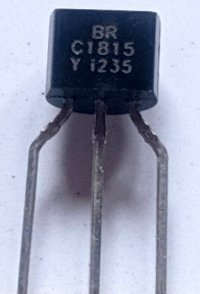
The Silicon Epitaxial NPN transistor is made by Toshiba and is commonly available in TO-92 Packaging as shown below. The important technical specifications of the 2SC1815 NPN Transistor is given below.
- It has Vceo =50v
- The collector current IC=150mA
- Absolute maximum ratings at Ta =25℃,
- Collector Base voltage Vcbo 60V
- Collector-Emitter voltage Vceo 50 V
- Emitter Base Voltage Vebo 5v
- General Purpose NPN Transistor
- DC Current Gain (hFE) 70 to 700
- Continuous Collector current (IC) is 0.15A
- Transition Frequency: 80MHz
- Collector power Dissipation PC=400mW
More details on the Transistor including its characteristics graph can be found in the 2SC1815 Datasheet
We are using 2 transistors for each section of the circuit as a dual-stage amplification configuration, a 560k resistance from VCC and a 47k resistor from the ground is used to make voltage divider circuit to provide the power/gain to the collector of the first transistor along with audio signal through 10uF capacitor from the volume potentiometer. In the emitter, there is a 2k variable resistor connected with a capacitor47uF and 1k resistor for frequency selection and audio clarification, the base of the first transistor is connected with the collector of the second transistor for future amplification. Finally, the output comes from the emitter of the second transistor through a 47uF capacitor with 2.7k and 1k resistor from the GND for noise filtration.
Building Pre-amplifier Circuit on Breadboard
Since the pre-amplifier circuit does not involve high current, we can construct the circuit on a breadboard. My breadboard connections look like as shown below. I have also marked the parts for easy understanding.
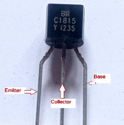
You can simply follow the above circuit diagram to build your own circuit. The most important component in our circuit is the C1815 NPN Transistor. The pinout of the transistor is shown below
Once the circuit is constructed, you can directly test it with your audio source. Do remember that this is an audio pre-amplifier circuit and not an amplifier on its own. Hence you have to connect the output of your pre-amplifier to an audio amplifier and then to your speaker system. For the testing of this project, I am using the LA4440 Audio Amplifier Board that we built in our previous tutorial. You can use any amplifier board of your choice, you can also build your own audio amplifier circuits of different wattage levels as required by your application.
The complete working of the Audio pre-amplifier is demonstrated in the video below. I hope you understood the tutorial and learned something useful if you have any questions, leave them on our forums or use the comment section below.

The circuit diagram currently on this page (2022-03-03) doesn't match the description. The circuit shown uses 2 ICs (LM4440J-K-E) and no transistors.