

The digital Revolution started in 1950 changes all the existing mechanical and analog electronic structures into digital computers. Since the growth of digital electronics has been exponential, today it is almost impossible for a person to resist using any electronic equipment. Starting from the alarm clock that wakes you up and the toaster that serves you breakfast, everything is a contribution from digital electronics. Thinking of all these it is really exciting to program our own stuff that could do simple yet useful tasks, like the Alarm Clock that we are going to build in this project with PIC Microcontroller. We have previously built alarm clock with other Microcontrollers:
- Raspberry Pi Alarm Clock using RTC Module DS1307
- Arduino Based Digital Clock with Alarm
- Alarm Clock using ATmega32 Microcontroller
This alarm clock will have an 16x2 LCD display which will display the current time and set time. We will use few push buttons to set the alarm time whenever required. The current time will be kept in track using the DS3231 RTC module and we will use IIC communication to get these values from the RTC module. We have already learnt about the RTC module and how to interface it with PIC. So it is recommended to read through that tutorial, we will be skipping most of the information covered in that tutorial.
Materials Required:
- Bread Board – 2Nos
- PIC16F877A
- 5V power source - Supply module
- 20 MHz crystal
- 33pf capacitor – 2Nos
- DS3231 RTC module
- 16*2 LCD display module
- 10K POT
- 10k and 1K resistor
- Push buttons – 5Nos
- Buzzer
- Connecting wires
Pre-requisites:
This project requires you know few basics about the PIC microcontroller and how to program it. We will use GPIOs, LCD display and RTC module for this project. So it is better to learn how to use these modules beforehand. The following links will help you to learn the same
- Writing your first program with PIC Microcontroller
- Interfacing LCD with PIC
- I2C communication using PIC
- DS3231 RTC interfacing with PIC
Circuit Diagram:
The circuit diagram for this PIC based Alarm Clock Project is shown below, which was created using the proteus software. The will also be used for simulation further in this project.

The five push buttons will act as an input for setting the alarm for the required time. So one end of all the push buttons are connected to ground and the other ends are connected to PORTB pin, internal pull-up resistor will be used on these pins to avoid the pins floating. The Buzzer will act as an output and will give us a beep when the alarm gets triggered and is connected to the PORT S pin. The current time is always kept in track by the DS3231 RTC module from which the PIC receives the data through I2C bus, so the SCL and SDA pins of the RTC module is connected to SCL and SDA pin of the PIC controller. A LCD display is attached to the PORTD of the PIC which is used to display the current time and set time. Learn more about using DS3231 RTC module with PIC here.
The complete circuit can be build over a breadboard. Since there are couple of dozen wires to connect so just have patience and make sure the connections are correct. My hardware set-up looked something like this below once I was done with the connections
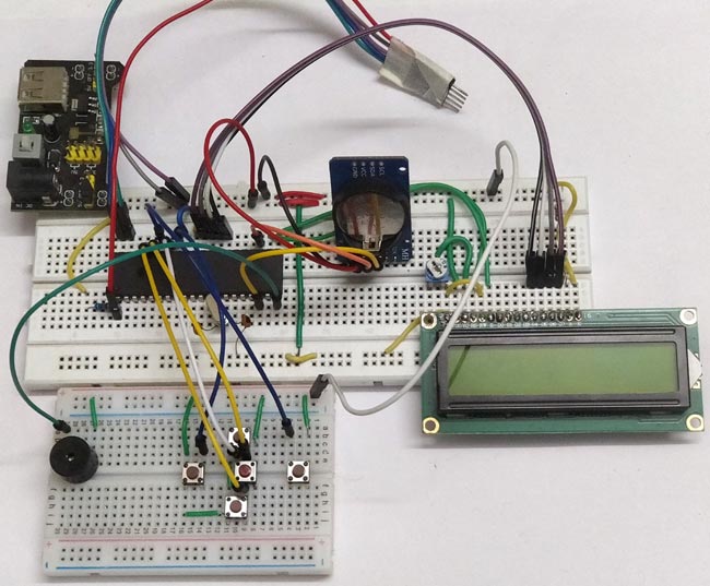
I have used a breadboard module and 12V adapter to power the module. This is my source of +5V supply voltage. Also I have to use two breadboards to keep the circuit clean. You can also solder the whole circuit to a perf board if you are looking to make more robust project.
Programming for Alarm Clock:
The complete PIC program for this Alarm Clock project can be found at the bottom of this page. This project also requires three libraries for using LCD, I2C and RTC with PIC. The complete code with header files can be downloaded from the ZIP file here and can be opened using MPLABX after extracting. Further below I am just explaining the main c file as small snippets. You can fall back to the above mentioned tutorials if you want to know how the header files work.
Before getting into the main program, we have to define the pins that we have used with more meaningful name. This way it will be easy to use them during programming. The pins defined in our program is shown below
//Define the LCD pins
#define RS RD2 //Reset pin of LCD
#define EN RD3 //Enable pin of LCD
#define D4 RD4 //Data bit 0 of LCD
#define D5 RD5 //Data bit 1 of LCD
#define D6 RD6 //Data bit 2 of LCD
#define D7 RD7 //Data bit 3 of LCD

//Define Buttons
#define MB RB1 //The middle button
#define LB RB0 //Left button
#define RB RB2 //Right button
#define UB RB3 //Upper Button
#define BB RB4 //Bottom button

//Define Buzz
#define BUZZ RD1 //Buzzer is connected to RD1
Inside the main function we start by declaring the Input and output pins. In our project the PORTB is used for push buttons which is an input device so we set their pins as inputs and PORTD is used for LCD and buzzer so we set their pins as Output. Also a pin should never be left floating meaning, the I/O pins should always be connected to either Ground or to the +5V voltage. In our case for the push buttons the pins will not be connected to anything when the button is not pressed so we use an internal pull-up resistor which sets the pin to High when not in use. This is done using the control registers as shown below
TRISD = 0x00; //Make Port D pins as outptu for LCD interfacing
TRISB = 0xFF; //Switchs are declared as input pins
OPTION_REG = 0b00000000; //Enable pull up Resistor on port B for switchs
BUZZ = 0; //Turn of buzzer
Since we have the LCD and I2C header file linked with the main program, we can start the LCD initialization by calling a simple function. The same can be done for I2C initialization as well. Here we are starting the I2C communication at 100kHz since the RTC module works with 100kHz.
Lcd_Start(); // Initialize LCD module
I2C_Initialize(100); //Initialize I2C Master with 100KHz clock
The below function is use to set the time and date on the RTC module, once the time and date is set remove this line. Else each time you start the program the time and date will be set again and again
//Remove the below line once time and date is set for the first time.
Set_Time_Date(); //set time and date on the RTC module
To indicate that the program is starting up we display a small intro screen which displays the name of project and website name as shown below
//Give an intro message on the LCD
         Lcd_Clear();
         Lcd_Set_Cursor(1,1);
         Lcd_Print_String("Alarm Clock");
         Lcd_Set_Cursor(2,1);
         Lcd_Print_String(" -Circuit Digest");
         __delay_ms(1500);
Next inside the while loop we need to read the current time and date from the RTC module, this can be done by just calling the below function.
Update_Current_Date_Time(); //Read the current date and time from RTC module
Calling the above function will update the variables sec, min and hour with the current value. In order to display them on the LCD screen we have to split them in to individual characters using the code below.
//Split the into char to display on lcd
        char sec_0 = sec % 10;
        char sec_1 = (sec / 10);
        char min_0 = min % 10;
        char min_1 = min / 10;
        char hour_0 = hour % 10;
        char hour_1 = hour / 10;
Next, we update the values over the LCD screen. The current time will be displayed in the first line and the set time at which the alarm has to be triggered is displayed on the second line. The code which does the same is shown below.
//Display the Current Time on the LCD screen
        Lcd_Clear();
        Lcd_Set_Cursor(1, 1);
        Lcd_Print_String("TIME: ");
        Lcd_Print_Char(hour_1 + '0');
        Lcd_Print_Char(hour_0 + '0');
        Lcd_Print_Char(':');
        Lcd_Print_Char(min_1 + '0');
        Lcd_Print_Char(min_0 + '0');
        Lcd_Print_Char(':');
        Lcd_Print_Char(sec_1 + '0');
        Lcd_Print_Char(sec_0 + '0');
        //Display the Date on the LCD screen
        Lcd_Set_Cursor(2, 1);
        Lcd_Print_String("Alarm: ");
        Lcd_Print_Char(alarm_val[0] + '0');
        Lcd_Print_Char(alarm_val[1] + '0');
        Lcd_Print_Char(':');
        Lcd_Print_Char(alarm_val[2] + '0');
        Lcd_Print_Char(alarm_val[3] + '0');
Now, we have displayed the time and set time on the LCD we have to check if the user is trying to set the alarm time. To do this the user has to press the middle button, so we will check if the middle button is pressed and toggle a variable to enter into alarm set mode. The same button will be pressed again to confirm that the values are set and in that case we have to come out of alarm set mode. So we use the below line of code to change the status of the variable set_alarm.
//Use middle button to check if alarm has to be set
        if (MB == 0 && set_alarm == 0) { //If middle button is pressed and alarm is not turned on
            while (!MB); //Wait till button is released
            set_alarm = 1; //start setting alarm value
        }
        if (MB == 0 && set_alarm == 1) { //If middle button is pressed and alarm is not turned off
            while (!MB); //Wait till button is released
            set_alarm = 0; //stop setting alarm value
        }
If the user has pressed the middle button, then it means that he is trying to set the alarm time. In this case the program enters into alarm set mode using the code above. Inside the alarm set mode if the user presses the left or right button it means we have to move the cursor left or right. To do this we simply increment of decrement the value of position at which the cursor has to be placed
          if (LB == 0) { //If left button is pressed
                while (!LB); //Wait till button is released
                pos--; //Then move the cursor to left
            }
            if (RB == 0) { //If right button is pressed
                while (!RB); //Wait till button is released
                pos++; //Move cursor to right
            }
While using a push button with a microcontroller or microprocessor there is one common problem to tackle. This problem is called as switch bouncing. That is when the button is pressed it might give noisy pulses to the MCU/MPU which might fake the MCU for multiple entries. This problem can be solved by adding a capacitor across the switch or by using a delay function as soon as the button press is detected. This type of solution is called de-bouncing. Here we have used a while loop to hold the program in place till the button is released. This is not a best de-bouncing solution but for us it will work just fine.
while (!RB);
Similar to the left and right button, we also have the upper and lower buttons which can be used to increase or decrease the value of alarm time. The code to do the same is shown below. Notice that each character of the set alarm time is addressed by the index value of the array. This was we can easily access the required character whose values has to be changed.
    if (UB == 0) { //If upper button is pressed
                while (!UB); //Wait till button is released
                alarm_val[(pos - 8)]++; //Increase that particular char value
            }
            if (BB == 0) { //If lower button is pressed
                while (!UB); //Wait till button is released
                alarm_val[(pos - 8)]--; //Decrease that particular char value
            }
Once the alarm time is set the user will press the middle button again. Then we can start comparing the current time with the set time. The comparison by checking if every single character of current time is equal to the character of the set time. If the values are equal then we trigger the alarm by setting the trigger_alarm variable else we just compare till it gets equal.
//IF alarm is set Check if the set value is equal to current value
        if (set_alarm == 0 && alarm_val[0] == hour_1 && alarm_val[1] == hour_0 && alarm_val[2] == min_1 && alarm_val[3] == min_0)
            trigger_alarm = 1; //Turn on trigger if value match
If the alarm is set we have to beep the buzzer to alert the user for alarm. This can be done by simply toggling the Buzzer at a regular interval as shown below.
     if (trigger_alarm) { //If alarm is triggered
            //Beep the buzzer
            BUZZ = 1;
            __delay_ms(500);
            BUZZ = 0;
            __delay_ms(500);
        }
Simulation:
This program can also be simulated using the proteus software. Just re-create the circuit shown above and load the hex file into the PIC. The hex code for this project can be found at the ZIP file that is linked here. A screen shot taken during the simulation is shown below

The simulation becomes very useful when you are trying to add new features to the project. You can also use the I2C debugger module to check what data is going in and coming out through the I2C bus. You can try pressing the buttons and also set the alarm time. When the set time is equal to the current time then the buzzer will go high.

Working of Digital Alarm Clock using PIC16F877A:
Build the circuit on the breadboard, get the code from the download link and compile it using MplabX and XC8 compiler. If you have downloaded the code from the ZIP file provided here, then you should have no problem compiling it since the header files are attached already.
After compiling upload the program to you hardware using the PicKit3 programmer. The connection to connect the pickit programmer to PIC IC is also shown in the circuit diagram. After the program is uploaded you should see the intro screen and then the time being displayed you can then use the push buttons to set the alarm time. My hardware set-up when powered looks like this below.
When the alarm time matches with the current time the buzzer will start beeping to alarm the user. The complete working can be found at the video below. The project has a plethora of options to build upon. The RTC module can keep track of any time and date, so you can perform a scheduled task at any time/date required. You can also connect an AC appliance like a fan or light and schedule it to turn ON or OFF when required. There are still much more you can build upon this project, let me know what idea comes to your mind as an upgrade to this project and I will be happy to hear from you.
Hope you understood the project and learnt something useful from the process. If you have any doubts in this project use the comment section to post them or use the forums for any technical help.
Complete Project Code
/*
 * Program: Alarm Clock Using PIC
 * Author: B.Aswinth Raj
 * More info: www.circuitdigest.com ;
 * Created on 11 May, 2018, 3:02 PM
 */
#pragma config FOSC = HS        // Oscillator Selection bits (HS oscillator)
#pragma config WDTE = OFF       // Watchdog Timer Enable bit (WDT disabled)
#pragma config PWRTE = ON       // Power-up Timer Enable bit (PWRT enabled)
#pragma config BOREN = ON       // Brown-out Reset Enable bit (BOR enabled)
#pragma config LVP = OFF        // Low-Voltage (Single-Supply) In-Circuit Serial Programming Enable bit (RB3 is digital I/O, HV on MCLR must be used for programming)
#pragma config CPD = OFF        // Data EEPROM Memory Code Protection bit (Data EEPROM code protection off)
#pragma config WRT = OFF        // Flash Program Memory Write Enable bits (Write protection off; all program memory may be written to by EECON control)
#pragma config CP = OFF         // Flash Program Memory Code Protection bit (Code protection off)
#define _XTAL_FREQ 20000000 //We are running on 20MHz crystal
//Define the LCD pins
#define RS RD2 //Reset pin of LCD
#define EN RD3 //Enable pin of LCD
#define D4 RD4 //Data bit 0 of LCD
#define D5 RD5 //Data bit 1 of LCD
#define D6 RD6 //Data bit 2 of LCD
#define D7 RD7 //Data bit 3 of LCD
//Define Buttons
#define MB RB1 //The middle button
#define LB RB0 //Left button
#define RB RB2 //Right button
#define UB RB3 //Upper Button
#define BB RB4 //Bottom button
//Define Buzz
#define BUZZ RD1 //Buzzer is connected to RD1
/*Set the current value of date and time below*/
int sec = 00;
int min = 55;
int hour = 10;
int date = 06;
int month = 05;
int year = 18;
/*Time and Date Set*/
/*Vars for Alarm clock*/
char set_alarm = 0;
char trigger_alarm = 0;
char pos = 8;
char jump = 0;
char alarm_h0 = 0;
char alarm_h1 = 0;
char alarm_m0 = 0;
char alarm_m1 = 0;
int alarm_val[4] = {0, 0, 0, 0};
/*End of var declaration*/
#include <xc.h>
#include "lcd.h" //Header for using LCD module
#include "PIC16F877a_I2C.h" // Header for using I2C protocal
#include "PIC16F877a_DS3231.h" //Header for using DS3231 RTC module
int main() {
    TRISD = 0x00; //Make Port D pins as outptu for LCD interfacing
    TRISB = 0xFF; //Switchs are declared as input pins
    OPTION_REG = 0b00000000; //Enable pull up Resistor on port B for switchs
    BUZZ = 0; //Turn of buzzer
    Lcd_Start(); // Initialize LCD module
    I2C_Initialize(100); //Initialize I2C Master with 100KHz clock
    //Remove the below line once time and date is set for the first time.
    Set_Time_Date(); //set time and date on the RTC module
    //Give an intro message on the LCD
         Lcd_Clear();
         Lcd_Set_Cursor(1,1);
         Lcd_Print_String("Alarm Clock");
         Lcd_Set_Cursor(2,1);
         Lcd_Print_String(" -Circuit Digest");
         __delay_ms(1500);
    while (1) {
        Update_Current_Date_Time(); //Read the current date and time from RTC module
        //Split the into char to display on lcd
        char sec_0 = sec % 10;
        char sec_1 = (sec / 10);
        char min_0 = min % 10;
        char min_1 = min / 10;
        char hour_0 = hour % 10;
        char hour_1 = hour / 10;
        //Display the Current Time on the LCD screen
        Lcd_Clear();
        Lcd_Set_Cursor(1, 1);
        Lcd_Print_String("TIME: ");
        Lcd_Print_Char(hour_1 + '0');
        Lcd_Print_Char(hour_0 + '0');
        Lcd_Print_Char(':');
        Lcd_Print_Char(min_1 + '0');
        Lcd_Print_Char(min_0 + '0');
        Lcd_Print_Char(':');
        Lcd_Print_Char(sec_1 + '0');
        Lcd_Print_Char(sec_0 + '0');
        //Display the Date on the LCD screen
        Lcd_Set_Cursor(2, 1);
        Lcd_Print_String("Alarm: ");
        Lcd_Print_Char(alarm_val[0] + '0');
        Lcd_Print_Char(alarm_val[1] + '0');
        Lcd_Print_Char(':');
        Lcd_Print_Char(alarm_val[2] + '0');
        Lcd_Print_Char(alarm_val[3] + '0');
        __delay_ms(50);
        //Use middle button to check if alarm has to be set
        if (MB == 0 && set_alarm == 0) { //If middle button is pressed and alarm is not turned on
            while (!MB); //Wait till button is released
            set_alarm = 1; //start setting alarm value
        }
        if (MB == 0 && set_alarm == 1) { //If middle button is pressed and alarm is not turned off
            while (!MB); //Wait till button is released
            set_alarm = 0; //stop setting alarm value
        }
        //If alarm has to be navigate through each digit
        if (set_alarm == 1) {
            if (LB == 0) { //If left button is pressed
                while (!LB); //Wait till button is released
                pos--; //Then move the cursor to left
            }
            if (RB == 0) { //If right button is pressed
                while (!RB); //Wait till button is released
                pos++; //Move cursor to right
            }
            if (pos >= 10) //eliminate ":" symbol if cursor reaches there
            {
                jump = 1; //Jump over the ":" symbol
            } else
                jump = 0; //get back to normal movement
            if (UB == 0) { //If upper button is pressed
                while (!UB); //Wait till button is released
                alarm_val[(pos - 8)]++; //Increase that particular char value
            }
            if (BB == 0) { //If lower button is pressed
                while (!UB); //Wait till button is released
                alarm_val[(pos - 8)]--; //Decrease that particular char value
            }
            Lcd_Set_Cursor(2, pos + jump);
            Lcd_Print_Char(95); //Display "_" to indicate cursor position
        }
        //IF alarm is set Check if the set value is equal to current value
        if (set_alarm == 0 && alarm_val[0] == hour_1 && alarm_val[1] == hour_0 && alarm_val[2] == min_1 && alarm_val[3] == min_0)
            trigger_alarm = 1; //Turn on trigger if value match
        if (trigger_alarm) { //If alarm is triggered
            //Beep the buzzer
            BUZZ = 1;
            __delay_ms(500);
            BUZZ = 0;
            __delay_ms(500);
        }
        __delay_ms(200);//Update interval
    }
    return 0;
}
Comments
Yes you can! but why? Do not
Yes you can! but why? Do not waste another 4 pins for the LCD.
If you want to use 8-bit mode just just alter the lcd.h header file accordingly. You can read the
https://circuitdigest.com/microcontroller-projects/16x2-lcd-interfacing…
for more information
I'm having a problem in this
I'm having a problem in this project and I need some help it would be highly appreciated. I tried to attach the program in the schematic diagram and I didn't change the program itself. But the lcd still display time : 00:00:00 alarm: 00:00, and even the push button isn't working. What seems to be the problem? Thank you for your response.
R2s15902fp
Dear sir plz
R2s15902fp hedar file& c .file & 16×2 lcd&push botton
How can I make alterations on
How can I make alterations on this same program to add 5 alarms in total. Also how can these alarms be set individually until there is a need to change the alarm again. Like in our phones today, we can set multiple alarms for everyday. You need not to set alarm again and again each day. Will this program run the same?
pic16f877a microcontroller based alarm clock
Hi there.. First of all would like to thank you for provide this code and circuits..am having some trouble here... i did everything as you said.. when i set the current time and alarm time it didnt run..it just show the value that i had programmed..and also i didnt get the I2C as u use down there in the circuit..what should i have to do... your help would be appreciated so much..
Question on alarm clock using RTC
Hello sir
I successfully done the project with 16x4 and three alarms.But want to ask question that my RTC not start from elapsed time after setting first time.It always start from what we set at intialising.What sholud I do to ticking it forever even after powero off on right and currunt time
?
Hi, could I replace PIC
Hi, could I replace PIC microcontroller with AVR128DB28?

can I use the LCD in 8 bit mode in this project?