
GPS modules are widely used in electronics applications to track the location based on longitude and latitude coordinates. Vehicle tracking system, GPS Clock, Accident Detection Alert System, traffic navigation, surveillance system etc. are few of the examples where GPS functionality is essential. GPS provides Altitude, Latitude, Longitude, UTC time and many other information about the particular location, which are taken from more than one satellite. To read data from GPS, a microcontroller is needed so here we are interfacing GPS module with AVR microcontroller Atmega16 and printing the longitude and latitude on 16x2 LCD display.
Components Required
- Atmega16/32
- GPS module (uBlox Neo 6M GPS)
- Long wire Antenna
- 16x2 LCD
- 2.2k Resistor
- 1000uf Capacitor
- 10uF capacitor
- Connecting wire
- LM7805
- DC Jack
- 12v DC Adaptor
- Burgstips
- PCB or General Purpose PCB
Ublox Neo 6M is a serial GPS module that provides location details through serial communication. It has four pins.
Pin | Description |
Vcc | 2.7 – 5V power supply |
Gnd | Ground |
TXD | Transmit Data |
RXD | Receive Data |
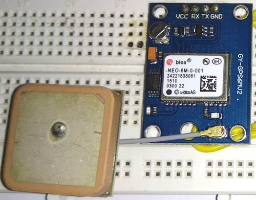
Ublox neo 6M GPS module is TTL compatible and its specifications is given below.
Capture time | Cool start : 27s , Hot start :1s |
Communication protocol | NMEA |
Serial communication | 9600bps , 8 data bits , 1 stop bit , no parity and no flow control |
Operating current | 45mA |
Getting Location Data from GPS
The GPS Module will transmit data in multiple strings at 9600 Baud Rate. If we use an UART terminal with 9600 Baud rate, we can see the data received by GPS.
GPS module sends the Realtime tracking position data in NMEA format (see the screenshot above). NMEA format consist several sentences, in which four important sentences are given below. More detail about the NMEA sentence and its data format can be found here.
- $GPGGA: Global Positioning System Fix Data
- $GPGSV: GPS satellites in view
- $GPGSA: GPS DOP and active satellites
- $GPRMC: Recommended minimum specific GPS/Transit data
Learn more about GPS data and NMEA strings here.
This is the data received by GPS when connected on 9600 baud rate.
$GPRMC,141848.00,A,2237.63306,N,08820.86316,E,0.553,,100418,,,A*73
$GPVTG,,T,,M,0.553,N,1.024,K,A*27
$GPGGA,141848.00,2237.63306,N,08820.86316,E,1,03,2.56,1.9,M,-54.2, M,,*74
$GPGSA,A,2,06,02,05,,,,,,,,,,2.75,2.56,1.00*02
$GPGSV,1,1,04,02,59,316,30,05,43,188,25,06,44,022,23,25,03,324,*76
$GPGLL,2237.63306,N,08820.86316,E,141848.00,A,A*65
When we use GPS module for tracking any location, we only need coordinates and we can find this in $GPGGA string. Only $GPGGA (Global Positioning System Fix Data) String is mostly used in programs and other strings are ignored.
$GPGGA,141848.00,2237.63306,N,08820.86316,E,1,03,2.56,1.9,M,-54.2,M,,*74
What is the meaning of that line?
Meaning of that line is:-
1. String always starts with a “$” sign
2. GPGGA stands for Global Positioning System Fix Data
3. “,” Comma indicates the separation between two values
4. 141848.00: GMT time as 14(hr):18(min):48(sec):00(ms)
5. 2237.63306,N: Latitude 22(degree) 37(minutes) 63306(sec) North
6. 08820.86316,E: Longitude 088(degree) 20(minutes) 86316(sec) East
7. 1 : Fix Quantity 0= invalid data, 1= valid data, 2=DGPS fix
8. 03 : Number of satellites currently viewed.
9. 1.0: HDOP
10. 2.56,M : Altitude (Height above sea level in meter)
11. 1.9,M : Geoids height
12. *74 : checksum
So we need No. 5 and No.6 to gather information about the module location or, where it is located. In this project we have used a GPS Library that provides some functions to extract the latitude and longitude so we don’t have to worry about that.
We have previously interface GPS with other microcontrollers:
- How to Use GPS with Arduino
- Raspberry Pi GPS Module Interfacing Tutorial
- Interfacing GPS Module with PIC Microcontroller
- Track A Vehicle on Google Maps using Arduino, ESP8266 & GPS
Check all the GPS related projects here.
Circuit Diagram
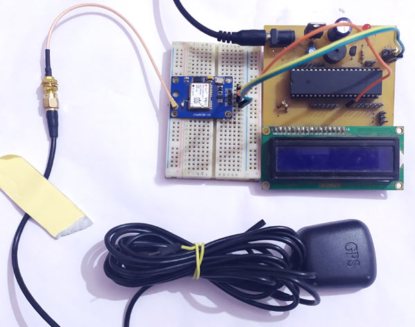
Circuit diagram for GPS interfacing with AVR Atemga16 microcontroller is give below:

Whole system is powered by a 12v DC Adapter, but the circuits works on 5v so the power supply is regulated to 5v by LM7805 voltage regulator. A 16x2 LCD is configured in 4-bit mode and its pin connections are shown in the circuit diagram. GPS is also powered by 5v and its tx pin is directly connected to Rx of Atmega16 microcontroller. A 8MHz crystal oscillator is used to clock the microcontroller.
Steps to Interface GPS with AVR Microcontroller
- Set the configurations of the microcontroller which include Oscillator configuration.
- Set the Desired port for LCD including DDR register.
- Connect the GPS module to the microcontroller using USART.
- Initialize the system UART in ISR mode, with 9600 baud rate and LCD in 4bit mode.
- Take two character arrays depending on the Length of Latitude and Longitude.
- Receive one character bit at a time and check whether it is started from $ or not.
- If $ is received then it is a string, we need to check $GPGGA, this 6 letters including $.
- If it is GPGGA, then receive the complete string and set flags.
- Then extract the latitude and longitude with directions in two arrays.
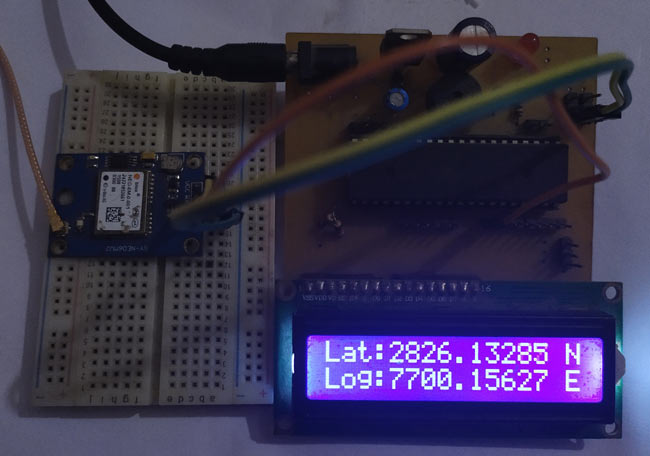
- Finally print the latitude and longitude arrays in LCD.
Code Explanation
Complete code with a Demonstration video is given at the end, here some important parts of the code are explained.
First of all include some required header in the code and then write MACROS of bitmask for LCD and UART config.
#define F_CPU 8000000ul
#include <avr/io.h>
#include <util/delay.h>
#include <avr/interrupt.h>
/***MACROS*/
#define USART_BAUDRATE 9600
#define BAUD_PRESCALE (((F_CPU / (USART_BAUDRATE * 16UL))) - 1)
#define LCDPORTDIR DDRB
#define LCDPORT PORTB
#define rs 0
#define rw 1
#define en 2
#define RSLow (LCDPORT&=~(1<<rs))
#define RSHigh (LCDPORT|=(1<<rs))
#define RWLow (LCDPORT&=~(1<<rw))
#define ENLow (LCDPORT&=~(1<<en))
#define ENHigh (LCDPORT|=(1<<en))
enum
{
     CMD=0,
     DATA,
};
Now declare and initialise some variables and arrays for storing GPS string, latitude longitude and flags.
char buf[100];
volatile char ind,flag,stringReceived;
char gpgga[]={'$','G','P','G','G','A'};
char latitude[12];
char logitude[12];
After it we have some LCD Driver function to drive LCD.
void lcdwrite(char ch,char r)
{
     LCDPORT=ch & 0xF0;
     RWLow;
     if(r == 1)
     RSHigh;
     else
     RSLow;
     ENHigh;
     _delay_ms(1);
     ENLow;
     _delay_ms(1);
     LCDPORT=ch<<4 & 0xF0;
     RWLow;
     if(r == 1)
     RSHigh;
     else
     RSLow;
     ENHigh;
     _delay_ms(1);
     ENLow;
     _delay_ms(1);
}
void lcdprint(char *str)
{
     while(*str)
     {
          lcdwrite(*str++,DATA);
          //__delay_ms(20);
     }
}
void lcdbegin()
{
     char lcdcmd[5]={0x02,0x28,0x0E,0x06,0x01};
     for(int i=0;i<5;i++)
     lcdwrite(lcdcmd[i], CMD);
}
After that we initialized the serial communication with GPS and compared the received string with "GPGGA":
void serialbegin()
{
     UCSRC = (1 << URSEL) | (1 << UCSZ0) | (1 << UCSZ1);
     UBRRH = (BAUD_PRESCALE >> 8);
     UBRRL = BAUD_PRESCALE;
     UCSRB=(1<<RXEN)|(1<<TXEN)|(1<<RXCIE);
}
ISR(USART_RXC_vect)
{
     char ch=UDR;
     buf[ind]=ch;
     ind++;
     if(ind<7)
     {
           if(buf[ind-1] != gpgga[ind-1])               // $GPGGA
                ind=0;
     }
     if(ind>=50)
           stringReceived=1;
}
void serialwrite(char ch)
{
     while ((UCSRA & (1 << UDRE)) == 0);
     UDR = ch;
}
Now if the received string is matched successfully with GPGGA then in main function extract and display the latitude and longitude coordinate of the location:
lcdwrite(0x80,0);
                lcdprint("Lat:");
                serialprint("Latitude:");
                for(int i=15;i<27;i++)
                {
                     latitude[i]=buf[i];
                     lcdwrite(latitude[i],1);
                     serialwrite(latitude[i]);
                     if(i==24)
                     {
                          lcdwrite(' ',1);
                          i++;
                     }
                }
                serialprintln(" ");
                lcdwrite(192,0);
                lcdprint("Log:");
                serialprint("Logitude:");
                for(int i=29;i<41;i++)
                {
                     logitude[i]=buf[i];
                     lcdwrite(logitude[i],1);
                     serialwrite(logitude[i]);
                     if(i==38)
                     {
                           lcdwrite(' ',1);
                           i++;
                     }
                }
So this is how the GPS module can be interfaced with ATmega16 to find the location coordinates. If you are new to GPS module and facing problems in getting this module to work check out the Neo 6M GPs module not working troubleshooting guide article to check out the common problems with this module and how to solve them. Find the complete code and working video of this project below.
Complete Project Code
/*
* GPS_interfacing.c
*
* Created: 8/26/2019 10:17:24 PM
*  Author: Evan
*/


#define F_CPU 8000000ul
#include <avr/io.h>
#include <util/delay.h>
#include <avr/interrupt.h>

/***MACROS*/

#define USART_BAUDRATE 9600
#define BAUD_PRESCALE (((F_CPU / (USART_BAUDRATE * 16UL))) - 1)

#define LCDPORTDIR DDRB
#define LCDPORT PORTB
#define rs 0
#define rw 1
#define en 2

#define RSLow (LCDPORT&=~(1<<rs))
#define RSHigh (LCDPORT|=(1<<rs))
#define RWLow (LCDPORT&=~(1<<rw))
#define ENLow (LCDPORT&=~(1<<en))
#define ENHigh (LCDPORT|=(1<<en))


enum
{
CMD=0,
DATA,
};

char buf[100];
volatile char ind,flag,stringReceived;
char gpgga[]={'$','G','P','G','G','A'};

char latitude[12];
char logitude[12];

void serialwrite(char ch);

void lcdwrite(char ch,char r)
{
LCDPORT=ch & 0xF0;
RWLow;
if(r == 1)
RSHigh;
else
RSLow;
ENHigh;
_delay_ms(1);
ENLow;
_delay_ms(1);

LCDPORT=ch<<4 & 0xF0;
RWLow;
if(r == 1)
RSHigh;
else
RSLow;
ENHigh;
_delay_ms(1);
ENLow;
_delay_ms(1);
}

void lcdprint(char *str)
{
while(*str)
{
lcdwrite(*str++,DATA);
//__delay_ms(20);
}
}

void lcdbegin()
{
char lcdcmd[5]={0x02,0x28,0x0E,0x06,0x01};
for(int i=0;i<5;i++)
lcdwrite(lcdcmd[i], CMD);
}

void serialbegin()
{
UCSRC = (1 << URSEL) | (1 << UCSZ0) | (1 << UCSZ1);
UBRRH = (BAUD_PRESCALE >> 8);
UBRRL = BAUD_PRESCALE;
UCSRB=(1<<RXEN)|(1<<TXEN)|(1<<RXCIE);
}

ISR(USART_RXC_vect)
{
char ch=UDR;
buf[ind]=ch;
ind++;
if(ind<7)
{
if(buf[ind-1] != gpgga[ind-1])               // $GPGGA
ind=0;
}
if(ind>=50)
stringReceived=1;
}

void serialwrite(char ch)
{
while ((UCSRA & (1 << UDRE)) == 0);
UDR = ch;
}

void serialprint(char *str)
{
while(*str)
{
serialwrite(*str++);
}
}

void serialprintln(char *str)
{
serialprint(str);
serialwrite(0x0d);
serialwrite(0x0a);
}

int main()
{
LCDPORTDIR=0xFF;
serialbegin();
serialprint("Saddam Khan");
lcdbegin();
lcdprint("GPS Interfacing");
lcdwrite(192,CMD);
lcdprint("Using Atmega16 ");
_delay_ms(2000);
lcdwrite(1,0);
lcdprint("Waiting for GPS");
_delay_ms(2000);
sei();
while(1)
{
if(stringReceived == 1)
{
cli();
serialprint("Received String:");
for(int i=0;i<ind;i++)
serialwrite(buf[i]);
ind=0;
stringReceived=0;
serialprintln(" ");
lcdwrite(0x80,0);
lcdprint("Lat:");
serialprint("Latitude:");
for(int i=15;i<27;i++)
{
latitude[i]=buf[i];
lcdwrite(latitude[i],1);
serialwrite(latitude[i]);
if(i==24)
{
lcdwrite(' ',1);
i++;
}
}
serialprintln(" ");
lcdwrite(192,0);
lcdprint("Log:");
serialprint("Logitude:");
for(int i=29;i<41;i++)
{
logitude[i]=buf[i];
lcdwrite(logitude[i],1);
serialwrite(logitude[i]);
if(i==38)
{
lcdwrite(' ',1);
i++;
}

}
serialprintln(" ");
serialFlush();
_delay_ms(2000);
sei();
}
}
return 0;
}

Sorry I have some doubts about the code, I get some errors and warnings, where is the serial flush function being created?