

In the area of renewable energy, solar energy is at the forefront, because producing energy by using the power of the sun is the easiest and commercially viable way of renewable energy. Speaking of solar panels, the output power of a solar panel output needs to be monitored in order to get optimum power output from the panels. This is why a real-time monitoring system becomes necessary. In a large solar power plant, it can also be used to monitor the power output from each panel which helps to identify the dust buildup. It also prevents any fault conditions during the time of operation. In some of our previous articles, we have built a few solar energy-related projects like a solar-powered cell phone charger and solar inverter circuit, etc. You can check those out if you are looking for more projects on solar power.
In this project, we will be making an IoT-based Solar Power Monitoring System by incorporating the MPPT (Maximum Power Point Tracker)-based battery charging technique, which will help to reduce charging time and improve efficiency. Also, we will measure the panel temperature, output voltage, and current to improve the safety aspect of the circuit. Finally, to top it all, we are going to use the ThingSpeak cloud services to monitor the output data from anywhere around the world. Note that this project is a continuation of the MPPT Solar Charge Controller Project that we built earlier. Here, we will be monitoring the output voltage, current, and power of the panel using the ESP32 IoT development board.
Choosing the Right Components for IoT Enabled Solar Power Monitor
With a solar monitor, it becomes very easy to monitor and detect faults in any solar system. This is why component selection becomes a very important part when designing such a system. Given below is the list of parts that we used.
- ESP32 dev board
- MPPT circuit (can be any solar circuit)
- A shunt resistor (for example 1 Ohm 1 watt - suitable for up to 1A of current)
- A lithium battery (7.4v preferred).
- Active Wi-Fi connection
- Temperature sensor for the solar panel
- Voltage divider circuit (see the description)
Esp32 Dev Board:
For an IoT-enabled application, it is essential to choose the right type kind of development board that will be able to process the data from its analog pins and send the data via any kind of connection protocol such as Wi-Fi or to the cloud server. We specifically selected ESP32 as it is a low-cost microcontroller with tons of features. Also, it has a built-in Wi-Fi radio through which we can connect to the internet very easily.
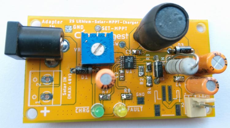
Solar Circuit:
A solar charging circuit is a circuit that gets higher voltage from the solar panel and converts it down to a charging voltage so that it can efficiently charge the battery. For this project, we will be using the LT3562 based MPPT Charge Controller Circuit Board that we have already made in one of our previous projects. But if you want to embed this IoT enable monitoring, you can use any kind of solar circuit. We have chosen this board because the circuit is equipped with Maximum Power Point Tracking (MPPT) which is beneficial for low power solar panel projects. It is an efficient way to charge a small lithium battery from a solar panel.
Shunt Resistor:
Any resistor follows the ohm's law which means if a certain amount of current flows through the resistor, a certain amount of voltage drop will appear. Shunt resistors are not an exception of this and it is specifically used to measure current flow. However, depending on the nominal current flow through the solar panel, choose a shunt resistor that will produce an adequate amount of voltage which can be measured by the microcontroller unit. But, at the same time, the wattage of the resistor is also an important thing. Selection of the shunt resistor wattage is also important.
The voltage drop can be calculated using the formula given below. This is known as Ohm's law-
V = I x R
V is the voltage that will be produced during 'I' i.e. the amount of current flow through the amount of resistor 'R'. For example, 1-ohm resistor will produce 1V of voltage drop when 1A of current flows through it.
For the wattage of the resistor, the formula given below can be used-
P=I2R
Where I is the maximum current flow, and the R is the resistor value. For 1A of current with 1 Ohms resistor, 1 watt is adequate for the power dissipation. However, this is useful for small solar panel projects but not at all suitable for solar grid related applications. In such a case, the non-invasive current measurement technique is actually what needs to be used. In such a case, the current flow can be accurately measured where a very low amount of current, as well as a very high amount of current, can be measured.
Lithium Battery:
The selection of the lithium battery is an essential part of any project which involves solar panels. Because the microcontroller unit that always remains on and constantly checks and submits the data requires at least a hundred milliampere of current for stable operation.
The battery capacity should be something that can power the microcontroller for at least 4-5 days when the sun is not shining because of the monsoon. It is also important that the charge current must be more than the load current from the battery perspective. It is quite unusual if someone connects 100mA of load with a battery and provides a charge current, which is less than that. To be on the safer side, we should have at least 5 times more charging current than the load current.
On the other hand, the battery voltage needs to be higher than any usual voltage regulator input voltage that requires for the microcontroller. For example, a 7.4V lithium battery could be connected across both 3.3V and 5.0V linear voltage regulator (as linear regulator requires higher dropout voltage more than the LDO and Switching.)
In our project, we used a 4000mAH battery with a 7.4V rating. We used a 5.0V regulator that provides sufficient current and voltage output for the ESP32.
Voltage Divider:
A voltage divider is an essential part of the Solar panel voltage measurement. One should choose a voltage divider that will divide the voltage as per the microcontroller I/O voltage input.
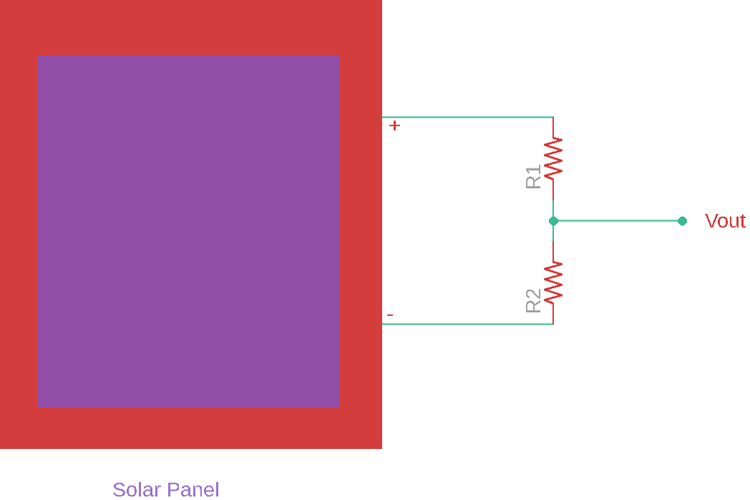
Choose the above resistors in such a way that the voltage divider output voltage should not exceed the microcontroller maxim I/O voltage (3.3V for ESP32). However, it is advised to use a potentiometer because it will provide flexibility to choose any solar panel higher or lower voltage rating and can easily set the voltage using a multimeter.
In our case, we have a potentiometer in the MPPT board circuit that acts as a voltage divider. We set the voltage divider with a division factor of 6V. We connected two multi-meters, one in the input and another in the output of the pot, and set the value that when the input voltage is 18V the output will be 3V since the nominal output voltage of the solar panel is 18V.
Temperature Sensor for the Solar Panel:
Solar panel power output has a direct connection with the temperature of the solar panel. Why? Because as a solar panel's temperature starts to increase the output current from the solar panel increases exponentially while the voltage output starts to reduce linearly.
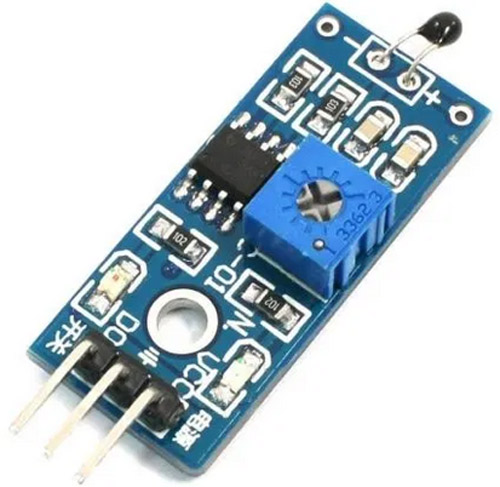
As per the power formula, Wattage is equal to voltage times current (W = V x A), decreasing output voltage also decreases the solar panel output power even after the increase of current flow. Now, the next question that comes to our mind is, how to measure solar temperature? Well, it is rather interesting as solar panels are generally exposed to the heat environment as it is exposed to direct sunlight and for obvious reasons. The best way to measure solar panel temperature is by using a flat surface temperature sensor. It is also suggested to use a K type thermocouple placed directly in the solar panel.
For our application, we have used a thermistor-based temperature sensor module, which is shown below.
Circuit Diagram for IoT based Solar Power Monitoring
The complete circuit diagram for the IoT Enabled Solar Power Monitor is shown below. The schematic is simple. The red dash-dot board is the MPPT board that we used for this project.

Setting up the ThingSpeak
Create an account with ThingSpeak and go to the “my channel” option, then click on the New Channel.
Create a new channel with the field names.
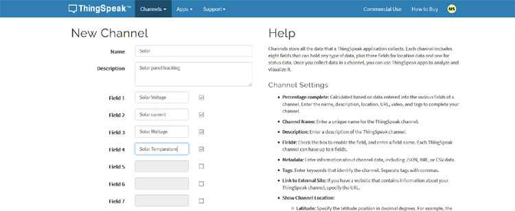
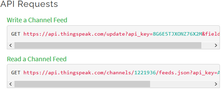
Now after setting the field, go to the API Keys field where the Write API Key is available. This key needs to be provided in the code as well as the channel ID.
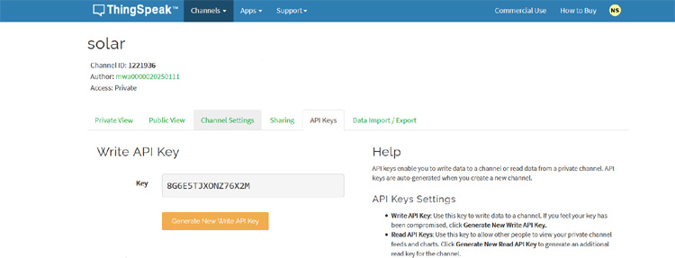
The ThingSpeak address can be found on the same page.
With the above steps, you can set up ThingSpeak very easily. If you want to learn more about ThingSpeak and its setup process, you can check out our previous articles on the topic.
Arduino Code for Solar Power Monitoring using ESP32
The complete ESP32 solar power monitoring code can be found at the bottom of this page. The code begins with defining your SSID, Password, and a few other constant parameters as shown below.
// define WiFi SSID & PWD for uplink.
#define WLAN_SSID   "xxxx"
#define WLAN_PASS   "xxxxxxxxxx"
In this field, the SSID and Password need to be set.
// resistance at 25 degrees C
#define THERMISTORNOMINAL 10000
// temp. for nominal resistance (almost always 25 C)
#define TEMPERATURENOMINAL 25
// The beta coefficient of the thermistor (usually 3000-4000)
#define BCOEFFICIENT 3950
// the value of the 'other' resistor
#define SERIESRESISTOR 10000
The thermistor nominal ohms is provided at the nominal temperature. Set this value depending on the datasheet of the thermistor. Put the Beta coefficient and series resistor value of the thermistor.
// define Analog for Current and Voltage
const int curr_an_pin = 35;
const int volt_an_pin = 34;
const int ntc_temp_an_pin = 33;
The PINs are defined over here.
#define thingSpeakAddress "xxxxxxxxx"
#define channelID xxxxx
#define writeFeedAPIKey "xxxxxxx"
#define readFeedAPIKey "xxxxxxx"
#define readFieldAPIKey "xxxxxxxx"
#define readStatusAPIKey "xxxxxxx"
Put the thingSpeakAddress, channelID, Write Feed API Key. The rest of the things are not required but are still useful if data needs to be received from the web.
void setup() {
  // put your setup code here, to run once:
  // set the serial port at 115200
  Serial.begin(115200);  //Initialize serial
  delay(1000);
  WiFi.mode(WIFI_STA);
  ThingSpeak.begin(client);  // Initialize ThingSpeak
  // todo: create a task to read an pin for get current & voltage and calculate watt and temperature of the solar panel
  xTaskCreate(
                wifi_task,               /* Task function. */
                "wifi_task",             /* String with name of task. */
                1024 * 2,                /* Stack size in bytes. */
                NULL,                    /* Parameter passed as input of the task */
                5,            /* Priority of the task. */
                NULL);                   /* Task handle. */
  Serial.print("Data Reading.");
}
In the above code, the ThingSpeak server is initialized and a task is created that will get the data related to the solar panel.
In the main loop, the solar current and voltage are sensed via an analog pin and the average is done.
  float solar_curr_adc_val = 0;
  float solar_volt_adc_val = 0;
  for (i = 0; i < NUMSAMPLES; i++) {
                curr_samples[i] = analogRead(curr_an_pin);
                volt_samples[i] = analogRead(volt_an_pin);
                temp_samples[i] = analogRead(ntc_temp_an_pin);
                delay(10);
  }
  // average all the samples out
  float curr_avg = 0;
  float volt_avg = 0;
  float temp_avg = 0;
  for (i = 0; i < NUMSAMPLES; i++) {
                curr_avg += curr_samples[i];
                volt_avg += volt_samples[i];
                temp_avg += temp_samples[i];
  }
  curr_avg /= NUMSAMPLES;
  volt_avg /= NUMSAMPLES;
  temp_avg /= NUMSAMPLES;
  //Serial.print("ADC VALUE = ");
  //Serial.println(ADC_VALUE);
  // convert adc value to voltages for get actual Current & Voltage.
  float solar_curr = (curr_avg * 3.3 ) / (4095);
  float solar_volt = (volt_avg * 3.3 ) / (4095);
  // by using a voltage divider we step down the actual voltage.
  //for that reason we multiply the 6 with avg voltage to get the actual voltage of the solar panel.
  solar_volt *= 6;
The solar voltage is submitted by multiplying with 6 as we created the voltage divider that will divide the input voltage by 6 times.
The temperature is generated from the thermistor using a logarithmic formation.
  // convert the value to resistance
  temp_avg = 4095 / temp_avg - 1;
  temp_avg = SERIESRESISTOR / temp_avg;
  //Serial.print("Thermistor resistance ");
  //Serial.println(temp_avg);
  float steinhart;
  steinhart = temp_avg / THERMISTORNOMINAL; // (R/Ro)
  steinhart = log(steinhart);  // ln(R/Ro)
  steinhart /= BCOEFFICIENT;  // 1/B * ln(R/Ro)
  steinhart += 1.0 / (TEMPERATURENOMINAL + 273.15); // + (1/To)
  steinhart = 1.0 / steinhart;  // Invert
  steinhart -= 273.15;  // convert absolute temp to C
The data is read every 15 seconds.
  delay(1000);
  count++;
  Serial.print(".");
  if (count >= 15 ) {
                count = 0;
                Serial.println("=========================================================================");
                Serial.print("Solar Voltage = ");
                Serial.println(solar_volt);
                Serial.print("Solar Current = ");
                Serial.println(solar_curr);
                float solar_watt = solar_volt * solar_curr;
                Serial.print("Solar Watt  = ");
                Serial.println(solar_watt);
                Serial.print("Solar Temperature  = ");
                Serial.println(steinhart);
                Serial.println("=========================================================================");
The data for respective fields is transmitted using the function Thing.Speak.setField(); when the WiFi is connected.
            if (WiFi.status() == WL_CONNECTED) {
                ThingSpeak.setField(1, solar_volt);
                ThingSpeak.setField(2, solar_curr);
                ThingSpeak.setField(3, solar_watt);
                ThingSpeak.setField(4, steinhart);
                // write to the ThingSpeak channel
                int x = ThingSpeak.writeFields(channelID, writeFeedAPIKey);
                if (x == 200) {
                Serial.println("Channels update successful.");
                }
                else {
                Serial.println("Problem updating channel. HTTP error code " + String(x));
                }
                } else {
                Serial.println("\r\n############################################################");
                Serial.println("Failed to update Data to thingSpeak Server. ");
                Serial.println("WiFi not connected...");
                Serial.println("############################################################\r\n");
                }
  Serial.print("Data Reading.");
  }
}
The Wi-Fi task created in the below code snippet-
void wifi_task( void * parameter ) {
  while (1) {
                if (WiFi.status() != WL_CONNECTED) {
                Serial.print("Attempting to connect to SSID: ");
                Serial.println(WLAN_SSID);
                while (WiFi.status() != WL_CONNECTED) {
                WiFi.begin(WLAN_SSID, WLAN_PASS);  // Connect to WPA/WPA2 network. Change this line if using open or WEP network
                Serial.print(".");
                delay(5000);
                }
                Serial.println("\nConnected.");
                Serial.println();
                Serial.println("WiFi connected");
                Serial.println("IP address: ");
                Serial.println(WiFi.localIP());
                }
                vTaskDelay( 1000 / portTICK_PERIOD_MS);
  }
  vTaskDelete(NULL);
}
Testing and Monitoring Data
The solar panel is connected with the circuit and placed in the sunlight for testing as shown below.
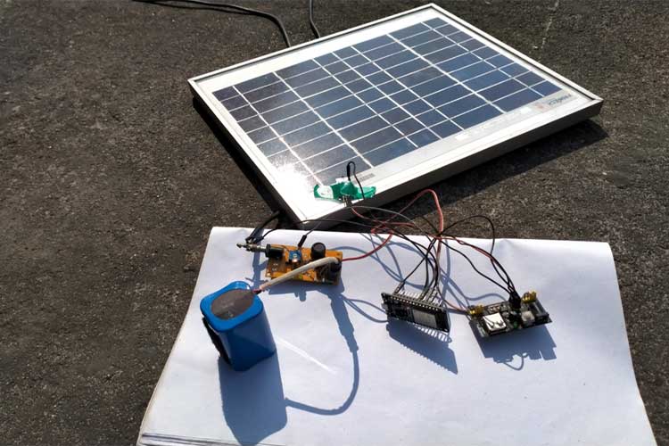
The complete working is demonstrated in the video below. Our circuit was able to read the output voltage, current, and power from the panel and update it live on the thingspeak channel as shown below.
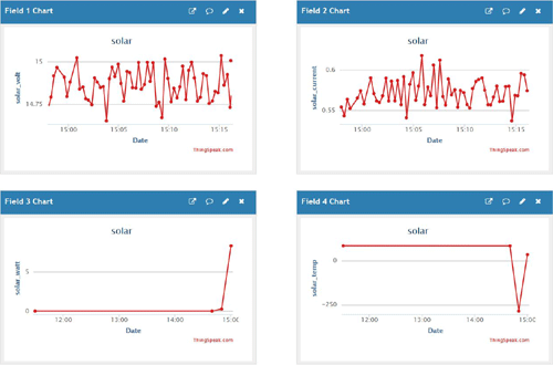
As we can see, 15-minute data is shown in the above graph. As this is an outdoor operation project, proper PCB along with an enclosed box needs to be used. The enclosure needs to be made in such a way that the circuit remains waterproof in rain. To modify this circuit or to discuss further aspects of this project, kindly use the active forum of Circuit Digest. Hope you enjoyed the tutorial and learned something useful.
Complete Project Code
#include <stdint.h>

#include "ThingSpeak.h"

#include <WiFi.h>

#include <stdio.h>

#include <stdlib.h>

// define WiFi SSID & PWD for uplink.

#define WLAN_SSID   "xxxx"

#define WLAN_PASS   "xxxxxxxxxx"

#define NUMSAMPLES 5

int curr_samples[NUMSAMPLES];

int volt_samples[NUMSAMPLES];

int temp_samples[NUMSAMPLES];

WiFiClient client;

// resistance at 25 degrees C

#define THERMISTORNOMINAL 10000

// temp. for nominal resistance (almost always 25 C)

#define TEMPERATURENOMINAL 25

// The beta coefficient of the thermistor (usually 3000-4000)

#define BCOEFFICIENT 3950

// the value of the 'other' resistor

#define SERIESRESISTOR 10000

// define Analog for Current and Voltage

const int curr_an_pin = 35;

const int volt_an_pin = 34;

const int ntc_temp_an_pin = 33;

int count = 0;

// thingSpeak Details

#define thingSpeakAddress "xxxxxxxxx"

#define channelID xxxxx

#define writeFeedAPIKey "xxxxxxx"

#define readFeedAPIKey "xxxxxxx"

#define readFieldAPIKey "xxxxxxxx"

#define readStatusAPIKey "xxxxxxx"

void setup() {

  // put your setup code here, to run once:

  // set the serial port at 115200

  Serial.begin(115200);  //Initialize serial

  delay(1000);

  WiFi.mode(WIFI_STA);

  ThingSpeak.begin(client);  // Initialize ThingSpeak

  // todo: create a task to read an pin for get current & voltage and calculate watt and temperature of the solar panel

  xTaskCreate(

                wifi_task,               /* Task function. */

                "wifi_task",             /* String with name of task. */

                1024 * 2,                /* Stack size in bytes. */

                NULL,                    /* Parameter passed as input of the task */

                5,            /* Priority of the task. */

                NULL);                   /* Task handle. */

  Serial.print("Data Reading.");

}

void loop() {

  // put your main code here, to run repeatedly:

  int i=0;

  float solar_curr_adc_val = 0;

  float solar_volt_adc_val = 0;

  for (i = 0; i < NUMSAMPLES; i++) {

                curr_samples[i] = analogRead(curr_an_pin);

                volt_samples[i] = analogRead(volt_an_pin);

                temp_samples[i] = analogRead(ntc_temp_an_pin);

                delay(10);

  }

  // average all the samples out

  float curr_avg = 0;

  float volt_avg = 0;

  float temp_avg = 0;

  for (i = 0; i < NUMSAMPLES; i++) {

                curr_avg += curr_samples[i];

                volt_avg += volt_samples[i];

                temp_avg += temp_samples[i];

  }

  curr_avg /= NUMSAMPLES;

  volt_avg /= NUMSAMPLES;

  temp_avg /= NUMSAMPLES;

  //Serial.print("ADC VALUE = ");

  //Serial.println(ADC_VALUE);

  // convert adc value to voltages for get actual Current & Voltage.

  float solar_curr = (curr_avg * 3.3 ) / (4095);

  float solar_volt = (volt_avg * 3.3 ) / (4095);

  // by using a voltage divider we step down the actual voltage.

  //for that reason we multiply the 6 with avg voltage to get the actual voltage of the solar panel.

  solar_volt *= 6;

  // convert the value to resistance

  temp_avg = 4095 / temp_avg - 1;

  temp_avg = SERIESRESISTOR / temp_avg;

  //Serial.print("Thermistor resistance ");

  //Serial.println(temp_avg);

  float steinhart;

  steinhart = temp_avg / THERMISTORNOMINAL;       // (R/Ro)

  steinhart = log(steinhart);                 // ln(R/Ro)

  steinhart /= BCOEFFICIENT;                           // 1/B * ln(R/Ro)

  steinhart += 1.0 / (TEMPERATURENOMINAL + 273.15); // + (1/To)

  steinhart = 1.0 / steinhart;                 // Invert

  steinhart -= 273.15;                           // convert absolute temp to C

  delay(1000);

  count++;

  Serial.print(".");

  if (count >= 15 ) {

                count = 0;

                Serial.println("=========================================================================");

                Serial.print("Solar Voltage = ");

                Serial.println(solar_volt);

                Serial.print("Solar Current = ");

                Serial.println(solar_curr);

                float solar_watt = solar_volt * solar_curr;

                Serial.print("Solar Watt  = ");

                Serial.println(solar_watt);

                Serial.print("Solar Temperature  = ");

                Serial.println(steinhart);

                Serial.println("=========================================================================");

                if (WiFi.status() == WL_CONNECTED) {

                ThingSpeak.setField(1, solar_volt);

                ThingSpeak.setField(2, solar_curr);

                ThingSpeak.setField(3, solar_watt);

                ThingSpeak.setField(4, steinhart);

                // write to the ThingSpeak channel

                int x = ThingSpeak.writeFields(channelID, writeFeedAPIKey);

                if (x == 200) {

                Serial.println("Channels update successful.");

                }

                else {

                Serial.println("Problem updating channel. HTTP error code " + String(x));

                }

                } else {

                Serial.println("\r\n############################################################");

                Serial.println("Failed to update Data to thingSpeak Server. ");

                Serial.println("WiFi not connected...");

                Serial.println("############################################################\r\n");

                }

  Serial.print("Data Reading.");

  }

}

void wifi_task( void * parameter ) {

  while (1) {

                if (WiFi.status() != WL_CONNECTED) {

                Serial.print("Attempting to connect to SSID: ");

                Serial.println(WLAN_SSID);

                while (WiFi.status() != WL_CONNECTED) {

                WiFi.begin(WLAN_SSID, WLAN_PASS);  // Connect to WPA/WPA2 network. Change this line if using open or WEP network

                Serial.print(".");

                delay(5000);

                }

                Serial.println("\nConnected.");

                Serial.println();

                Serial.println("WiFi connected");

                Serial.println("IP address: ");

                Serial.println(WiFi.localIP());

                }

                vTaskDelay( 1000 / portTICK_PERIOD_MS);

  }

  vTaskDelete(NULL);

}
Comments
for 12V battery you can use
for 12V battery you can use 12 Ohn 1 watt - for up to 1 A current
please i am stuck compiling
please i am stuck compiling your sketch to my esp8266. though your sketch indicated esp32 board. Aside the board, what is wrong with the sketch base on the picture below so i can get it working for my project please.

#include <stdint.h>
#include <stdint.h>
#include "ThingSpeak.h"
#include <WiFi.h>
#include <stdio.h>
#include <stdlib.h>
// define WiFi SSID & PWD for uplink.
#define WLAN_SSID "xxxx"
#define WLAN_PASS "xxxxxxxxxx"
#define NUMSAMPLES 5
int curr_samples[NUMSAMPLES];
int volt_samples[NUMSAMPLES];
int temp_samples[NUMSAMPLES];
WiFiClient client;
// resistance at 25 degrees C
#define THERMISTORNOMINAL 10000
// temp. for nominal resistance (almost always 25 C)
#define TEMPERATURENOMINAL 25
// The beta coefficient of the thermistor (usually 3000-4000)
#define BCOEFFICIENT 3950
// the value of the 'other' resistor
#define SERIESRESISTOR 10000
// define Analog for Current and Voltage
const int curr_an_pin = 35;
const int volt_an_pin = 34;
const int ntc_temp_an_pin = 33;
int count = 0;
// thingSpeak Details
#define thingSpeakAddress "xxxxxxxxx"
#define channelID xxxxx
#define writeFeedAPIKey "xxxxxxx"
#define readFeedAPIKey "xxxxxxx"
#define readFieldAPIKey "xxxxxxxx"
#define readStatusAPIKey "xxxxxxx"
void setup() {
// put your setup code here, to run once:
// set the serial port at 115200
Serial.begin(115200); //Initialize serial
delay(1000);
WiFi.mode(WIFI_STA);
ThingSpeak.begin(client); // Initialize ThingSpeak
// todo: create a task to read an pin for get current & voltage and calculate watt and temperature of the solar panel
xTaskCreate(
wifi_task, /* Task function. */
"wifi_task", /* String with name of task. */
1024 * 2, /* Stack size in bytes. */
NULL, /* Parameter passed as input of the task */
5, /* Priority of the task. */
NULL); /* Task handle. */
Serial.print("Data Reading.");
}
void loop() {
// put your main code here, to run repeatedly:
int i=0;
float solar_curr_adc_val = 0;
float solar_volt_adc_val = 0;
for (i = 0; i < NUMSAMPLES; i++) {
curr_samples[i] = analogRead(curr_an_pin);
volt_samples[i] = analogRead(volt_an_pin);
temp_samples[i] = analogRead(ntc_temp_an_pin);
delay(10);
}
// average all the samples out
float curr_avg = 0;
float volt_avg = 0;
float temp_avg = 0;
for (i = 0; i < NUMSAMPLES; i++) {
curr_avg += curr_samples[i];
volt_avg += volt_samples[i];
temp_avg += temp_samples[i];
}
curr_avg /= NUMSAMPLES;
volt_avg /= NUMSAMPLES;
temp_avg /= NUMSAMPLES;
//Serial.print("ADC VALUE = ");
//Serial.println(ADC_VALUE);
// convert adc value to voltages for get actual Current & Voltage.
float solar_curr = (curr_avg * 3.3 ) / (4095);
float solar_volt = (volt_avg * 3.3 ) / (4095);
// by using a voltage divider we step down the actual voltage.
//for that reason we multiply the 6 with avg voltage to get the actual voltage of the solar panel.
solar_volt *= 6;
// convert the value to resistance
temp_avg = 4095 / temp_avg - 1;
temp_avg = SERIESRESISTOR / temp_avg;
//Serial.print("Thermistor resistance ");
//Serial.println(temp_avg);
float steinhart;
steinhart = temp_avg / THERMISTORNOMINAL; // (R/Ro)
steinhart = log(steinhart); // ln(R/Ro)
steinhart /= BCOEFFICIENT; // 1/B * ln(R/Ro)
steinhart += 1.0 / (TEMPERATURENOMINAL + 273.15); // + (1/To)
steinhart = 1.0 / steinhart; // Invert
steinhart -= 273.15; // convert absolute temp to C
delay(1000);
count++;
Serial.print(".");
if (count >= 15 ) {
count = 0;
Serial.println("=========================================================================");
Serial.print("Solar Voltage = ");
Serial.println(solar_volt);
Serial.print("Solar Current = ");
Serial.println(solar_curr);
float solar_watt = solar_volt * solar_curr;
Serial.print("Solar Watt = ");
Serial.println(solar_watt);
Serial.print("Solar Temperature = ");
Serial.println(steinhart);
Serial.println("=========================================================================");
if (WiFi.status() == WL_CONNECTED) {
ThingSpeak.setField(1, solar_volt);
ThingSpeak.setField(2, solar_curr);
ThingSpeak.setField(3, solar_watt);
ThingSpeak.setField(4, steinhart);
// write to the ThingSpeak channel
int x = ThingSpeak.writeFields(channelID, writeFeedAPIKey);
if (x == 200) {
Serial.println("Channels update successful.");
}
else {
Serial.println("Problem updating channel. HTTP error code " + String(x));
}
} else {
Serial.println("\r\n############################################################");
Serial.println("Failed to update Data to thingSpeak Server. ");
Serial.println("WiFi not connected...");
Serial.println("############################################################\r\n");
}
Serial.print("Data Reading.");
}
}
void wifi_task( void * parameter ) {
while (1) {
if (WiFi.status() != WL_CONNECTED) {
Serial.print("Attempting to connect to SSID: ");
Serial.println(WLAN_SSID);
while (WiFi.status() != WL_CONNECTED) {
WiFi.begin(WLAN_SSID, WLAN_PASS); // Connect to WPA/WPA2 network. Change this line if using open or WEP network
Serial.print(".");
delay(5000);
}
Serial.println("\nConnected.");
Serial.println();
Serial.println("WiFi connected");
Serial.println("IP address: ");
Serial.println(WiFi.localIP());
}
vTaskDelay( 1000 / portTICK_PERIOD_MS);
}
vTaskDelete(NULL);
}
can you tell me shunt
can you tell me shunt resistor value for 50W (4A, 12V nominal) (open circuit voltage: 18 to 20V) solar panel ?

can you tell me shunt resistor value for 12v solar panel ?