

A current transformer is a type of instrumental transformer specially designed to transform alternating current in its secondary winding, and the amount of current produced is directly proportional to the current in the primary winding. This type of current transformer is designed to non-invisibly measure current from the high voltage subsystem or where a high amount of current is flowing through the system. A current transformer's job is to convert the high amount of current to a lower amount of current which can be easily measured by a microcontroller or an Analog meter. We previously explained current measurement using the current transformer in different types of current sensing techniques article.
Here we will learn this current sensing technique in detail and wire up a current transformer to measure AC current with the help of an Arduino. We will also learn to determine the turns ratio of an unknown current transformer.
Current Transformer
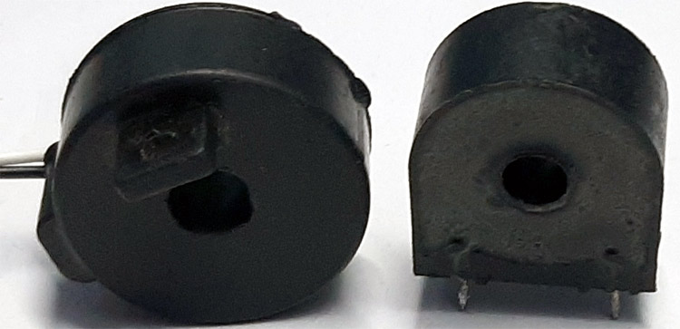
As I have previously mentioned, a current transformer is a transformer designed to measure current. The above showing two transformers that I currently have is called a window-type current transformer or commonly known as a core-balance transformer.
How Current Transformer Works?
The basic principle of the current transformer is the same as a voltage transformer, alike voltage transformer the current transformer also consists of a primary winding and a secondary winding. When an alternating electric current passes through the transformer's primary winding, alternating magnetic flux is produced, which induces an alternating current in the secondary winding at this point you can say its almost the same as a voltage transformer if you are thinking this here is the difference.
Generally, a current transformer is always in a short circuit condition with the assistance of a burden resistor, also, the current flowing on the secondary winding only depends on the primary current flowing through the conductor.
Current Transformer Construction
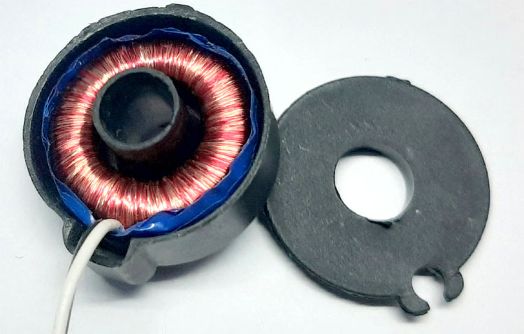
To give you a better understanding, I have torn down one of my current transformers which you can see in the above image.
It can be seen in the image that a very thin wire is wounded around a toroidal core material, and a set of wires are coming out of the transformer. The prime winding is only a single wire which is connected in series with the load and carries the bulk current flowing through the load.
Current Transformer Ratio

By placing a wire inside the window of the current transformer, we can form a single loop and the turns ratio becomes 1:N.
Like any other transformer, a current transformer must satisfy the amp-turn ratio equation which is shown below.
TR = Np / Ns = Is / Ip
Where,
TR =Trans Ratio
Np = Number of primary Turns
Ns = Number of Secondary Turns
Ip = Current in primary Winding
Is = Current in Secondary Winding
To find the secondary current, rearrange the equation to
Is = Ip x (Np/NS)
As you can see in the above image, the primary winding of the transformer consists of one winding and the secondary winding of the transformer consists of thousands of windings if we assume 100A of current is flowing through the primary winding, the secondary current will be 5A. So, the ratio between primary to secondary becomes 100A to 5A or 20:1. So, it can be said that the primary current is 20 times higher than that of secondary current.
Note! Please note that the current ratio is not the same as the turns ratio.
Now all the basic theory out of the way, we can turn our focus back to calculating the turns ratio of the current transformer in hand.
Current Transformer Error
Every circuit has some errors. Current transformers are no different; there exist various errors in a current transformer. Some of which are described below
Ratio Error in Current Transformer
The primary current of the current transformer is not exactly equal to the secondary current multiplied by the turns ratio. A portion of the current is consumed by the core of the transformer to get it to an excitation state.
Phase Angle Error in Current Transformer
For an ideal CT, the primary and secondary current vector is zero. But in an actual Current Transformer, there will always be a difference because the primary has to supply the excitation current to the core and there will be a small phase difference.

How to Reduce Error in a Current Transformer?
It's always necessary to reduce errors in a system to achieve better performance. So, by below steps, one can achieve that
- Using a core with a high permeability with a low hysteresis magnetic material.
- The burden resistor value must be very close to the calculated value.
- The internal impedance of the secondary can be lowered.
Back Calculating the Turns Ratio of a Current Transformer
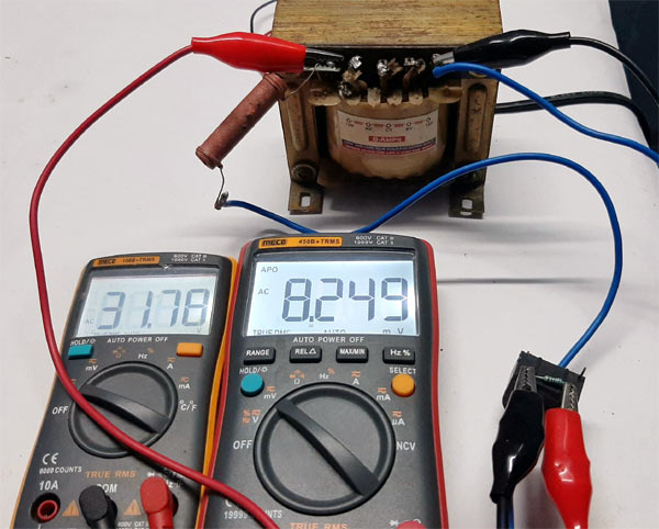
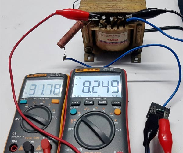
The test setup has been shown in the above image which I have used to figure out the turns ratio.
As I have mentioned before, the Current Transformer (CT) I own does not have any specification or part number just because I salvaged them from a broken household electric meter. So, at this point, we need to know the turns ratio to set the value of the Burden Resistor properly, otherwise, all sorts of issues will be introduced in the system, which I will talk more about later in the article.
With the help of the ohm's law, the turns ratio can be easily figured out but before that, I need to measure the big 10W, 1K resistor which is acting as a load in the circuit, and I also need to get an arbitrary burden resistor to figure out the turns ratio.
The Load Resistor

The Burden Resistor

Summary of all the component values during the time of testing
Input Voltage Vin = 31.78 V
Load Resistance RL = 1.0313 KΩ
Burden Resistance RB = 678.4 Ω
Output Voltage Vout = 8.249 mV or 0.008249 V
The current flowing through the load resistor is
I = Vin / RL
I = 31.78 / 1.0313 = 0.03080A or 30.80 mA
So now we know the input current, which is 0.03080A or 30.80 mA
Let's find out the output current
I = Vout / RB
I =  0.008249 / 678.4 = 0.00001215949A or 12.1594 uA
Now, to calculate the turns ratio, we need to divide the primary current with the secondary current.
Turns Ratio n = Primary Current / Secondary current
n = 0.03080 / 0.0000121594 = 2,533.1972
So the Current Transformer consists of 2500 turns (round off value)
Note! Please note the errors are mostly due to my ever-changing input voltage and multimeter tolerance.
Calculating a Suitable Burden Resistor Size
The CT used here is a current output type. So to measure current, it needs to be converted into a voltage type. This article, in the openenergymonitor website, gives a great idea about how we can do that so I am going to follow the article
Burden Resistor (ohms) = (AREF * CT TURNS) / (2√2 * max primary current)
Where,
AREF = Analog reference voltage of the ADS1115 module which is set to 4.096V.
CT TURNS = No. of secondary turns, which we have previously calculated.
Max Primary Current = maximum primary current, which will be flown through the CT.
Note! Every CT has a Maximum current rating exceeding that rating will lead to core saturation and ultimately linearity errors which will lead to measurement error
Note! The maximum current rating of the household energy meter is 30A, so I am going for that value.
Burden Resistor (ohms) = (4.096 * 2500) / (2√2 * 30) = 120.6 Ω
120.6Ω is not a common value, that is why I am going to use three resistors in series to get 120Ω resistor-value. After connecting the resistors to the CT, I did some tests to calculate the maximum output voltage from the CT.
After the test, it is observed that if 1mA current is fed through the primary of the current transformer, the output was 0.0488mV RMS. With that, we can calculate if 30A current is flown through the CT the output voltage will be 30000 * 0.0488 = 1.465V.
Now, with the calculations done, I have set ADC gain to 1x gain which is +/- 4.096V, which gives us 0.125mV full-scale resolution. With that, we will be able to calculate the minimum current that can be measured with this setup. Which turned out to be 3mA because the ADC resolution was set to 0.125mV.
Components Required
Write all the component without table
|
Sl.No |
Parts |
Type |
Quantity |
|
1 |
CT |
Window Type |
1 |
|
2 |
Arduino Nano |
Generic |
1 |
|
3 |
AD736 |
IC |
1 |
|
4 |
ADS1115 |
16-Bit ADC |
1 |
|
5 |
LMC7660 |
IC |
1 |
|
6 |
120Ω, 1% |
Resistor |
1 |
|
7 |
10uF |
Capacitor |
2 |
|
8 |
33uF |
Capacitor |
1 |
|
9 |
Breadboard |
Generic |
1 |
|
10 |
Jumper Wires |
Generic |
10 |
Circuit Diagram
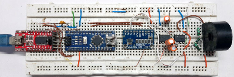
The below schematic shows the hookup guide for current measurement using the current transformer

This is how the circuit will look on the breadboard.
Current Measurement Circuit Construction
In a previous tutorial, I have shown you how to accurately measure True RMS voltage with the help of AD736 IC and how to configure a switched capacitor voltage converter circuit that generates a negative voltage from an input positive voltage, in this tutorial, we are using both the ICs from these tutorials.
For this demonstration, the circuit is constructed on a solderless Breadboard, with the help of the schematic; also, the DC voltage is measured with the help of a 16bit ADC for better accuracy. And as I am demonstrating the circuit on a breadboard to reduce the parasitic, I have used as many jumper cables as possible.
Arduino Code for Current Measurement
Here Arduino is used to displaying the measured values to the serial monitor window. But with a little modification in the code, one can very easily display the values on 16x2 LCD. Learn the interfacing of 16x2 LCD with Arduino here.
Complete code for the current transformer can be found at the end of this section. Here important parts of the program are explained.
We start by including all the required libraries files. The Wire library is used to communicate between the Arduino and the ADS1115 module and the Adafruit_ADS1015 library helps us to read data and write instructions to the module.
#include <Wire.h>
#include <Adafruit_ADS1015.h>
Next, define the MULTIPLICATION_FACTOR which is used to calculate the current value from the ADC value.
#define MULTIPLICATION_FACTOR 0.002734 /* factor to calculate actual current value */
Adafruit_ADS1115 ads;  /* Use this for the 16-bit version ADS1115 */
The 16-bit ADC spits outs 16-bit long integers so the int16_t variable is used. Three other variables are used, one to store the RAW value for the ADC, one to display the actual voltage in the ADC pin and finally one to display this voltage value to current value.
int16_t  adc1_raw_value; /* variable to store raw ADC value*/
float measured_voltae; /* variable to store measured voltage*/
float current; /* variable to store calculated current*/
Begin the setup section of the code by enabling the serial output with 9600 baud. Then print the gain of the ADC which is set; this is because voltage more than the defined value can certainly damage the device.
Now set the ADC gain with the ads.setGain(GAIN_ONE); the method which sets the 1-bit resolution to 0.125mV
After that, the ADC begin method is called which sets everything up in the hardware module and stats conversion.
void setup(void)
{
  Serial.begin(9600);
  Serial.println("Getting single-ended readings from AIN0..3"); //some debug information
  Serial.println("ADC Range: +/- 4.096V (1 bit = 2mV/ADS1015, 0.125mV/ADS1115)");
  // The ADC input range (or gain) can be changed via the following
  // functions, but be careful never to exceed VDD +0.3V max, or to
  // exceed the upper and lower limits if you adjust the input range!
  // Setting these values incorrectly may destroy your ADC!
  //                                                                ADS1015  ADS1115
  //                                                                -------  -------
  // ads.setGain(GAIN_TWOTHIRDS);  // 2/3x gain +/- 6.144V  1 bit = 3mV      0.1875mV (default)
     ads.setGain(GAIN_ONE);        // 1x gain   +/- 4.096V  1 bit = 2mV      0.125mV
  //ads.setGain(GAIN_TWO);        // 2x gain   +/- 2.048V  1 bit = 1mV      0.0625mV
  // ads.setGain(GAIN_FOUR);       // 4x gain   +/- 1.024V  1 bit = 0.5mV    0.03125mV
  // ads.setGain(GAIN_EIGHT);      // 8x gain   +/- 0.512V  1 bit = 0.25mV   0.015625mV
  // ads.setGain(GAIN_SIXTEEN);    // 16x gain  +/- 0.256V  1 bit = 0.125mV  0.0078125mV
  ads.begin();
}
In the loop section, I read the raw ADC value and store it to the previously mentioned variable for later use. Then convert the raw ADC value to voltage values for measurement and calculate the current value and display it to the serial monitor window.
void loop(void)
{
  adc1_raw_value = ads.readADC_SingleEnded(1);
  measured_voltae = adc1_raw_value * (4.096 / 32768);
  current = adc1_raw_value * MULTIPLICATION_FACTOR;
  Serial.print("ADC Value: "); Serial.println(adc1_raw_value);
  Serial.print("Measured Voltage: "); Serial.println(measured_voltae);Serial.println("V");
  Serial.print("Calculated Current: "); Serial.print(val,5); Serial.println("A");
  Serial.println(" ");
  delay(500);
}
Note! If you do not have the library for the ADS1115 module, you need to include the library in the Arduino IDE, you can find the library in this GitHub repository.
Complete Arduino code is given below:
#include <Wire.h>
#include <Adafruit_ADS1015.h>
#define MULTIPLICATION_FACTOR 0.002734 /* factor to calculate actual current value */
#define ADC_MAX_VALUE 32768 /* maximum value that ADC produces*/
#define ADC_GAIN 4.096
Adafruit_ADS1115 ads;  /* Use this for the 16-bit version ADS1115 */
int16_t  adc1_raw_value; /* variable to store raw ADC value*/
float measured_voltae; /* variable to store measured voltae*/
float current; /* variable to store calculated current*/
void setup(void)
{
  Serial.begin(9600);
  Serial.println("Getting single-ended readings from AIN0..3"); //some debug information
  Serial.println("ADC Range: +/- 4.096V (1 bit = 2mV/ADS1015, 0.125mV/ADS1115)");
  // The ADC input range (or gain) can be changed via the following
  // functions, but be careful never to exceed VDD +0.3V max, or to
  // exceed the upper and lower limits if you adjust the input range!
  // Setting these values incorrectly may destroy your ADC!
  //                                                                ADS1015  ADS1115
  //                                                                -------  -------
  // ads.setGain(GAIN_TWOTHIRDS);  // 2/3x gain +/- 6.144V  1 bit = 3mV      0.1875mV (default)
     ads.setGain(GAIN_ONE);        // 1x gain   +/- 4.096V  1 bit = 2mV      0.125mV
  //ads.setGain(GAIN_TWO);        // 2x gain   +/- 2.048V  1 bit = 1mV      0.0625mV
  // ads.setGain(GAIN_FOUR);       // 4x gain   +/- 1.024V  1 bit = 0.5mV    0.03125mV
  // ads.setGain(GAIN_EIGHT);      // 8x gain   +/- 0.512V  1 bit = 0.25mV   0.015625mV
  // ads.setGain(GAIN_SIXTEEN);    // 16x gain  +/- 0.256V  1 bit = 0.125mV  0.0078125mV
  ads.begin();
}
void loop(void)
{
  adc1_raw_value = ads.readADC_SingleEnded(1);
  measured_voltae = adc1_raw_value * (ADC_GAIN / ADC_MAX_VALUE);
  current = adc1_raw_value * MULTIPLICATION_FACTOR;
  Serial.print("ADC Value: "); Serial.println(adc1_raw_value);
  Serial.print("Measured Voltage: "); Serial.print(measured_voltae);Serial.println("V");
  Serial.print("Calculated Current: "); Serial.print(current,5); Serial.println("A");
  Serial.println(" ");
  delay(500);
}
Testing the Circuit
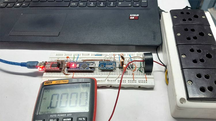
Tools used to test the circuit
- 2 60W incandescent light bulb
- Meco 450B+TRMS Multimeter
To test the circuit the above setup was used. The current is flowing from the CT to the multimeter, then it is going back to the main's power line.
If you are wondering what an FTDI board is doing in this setup, let me tell you that the onboard USB to serial converter was not working, so I had to use an FTDI converter as a USB to serial converter.
Further Enhancements
The few mA errors you saw in the video (given below) are just because I have made the circuit in a breadboard, so there were many ground issues.
I hope you liked this article and learned something new out of it. If you have any doubt, you can ask in the comments below or can use our forums for detailed discussion.
Comments
Hi! I have two questions:
Hi! I have two questions:
1.) How did you calculate the multiplication factor?
" MULTIPLICATION_FACTOR 0.002734 /* factor to calculate actual current value */ "
2.) Could I use the ADC of the microcontroller? It has only a 10bit ADC, and it is OK for me. Of course, I have to use an external reference voltage source.

Hi
Firstly, thanks for a great article.
I believe you have a mistake in your formula for TR. You have this:
The right side of the formula is inverted. It should be
Correcting this will then match your (correct) converted formula
Cheers
Brian