

Internet of Things (IoT) has seen exponential growth over the past couple of years. A new study from International Data Corporation (IDC) estimates that there will be almost 42 billion connected devices within the year 2025, generating over 80 zettabytes (ZB) of data. As the number of IoT devices grows; the amount of data grows, along with that, grows the need for superior network instruments; which can support this load.
However, if we consider a common host (like a generic router), it can connect to a limited number of nodes, less than 32 to be exact. And with an increasing number of IoT devices that could be in our home or industry, this is not sufficient. Currently, there are two solutions to this problem: The first one is to use a Mesh Router that can handle a lot more connections compared to a generic one, or we can use a network protocol known as Mesh Network.
So in this article, we are going to make a simple ESP Mesh network setup that consists of four ESP devices that will communicate with each other with the help of a Wi-Fi Mesh Network. And finally, we are going to connect a single ESP to our laptop in order to get data from all the four sensors on the network. Note that we will be using both the ESP32 and ESP8266 boards in this tutorial so that you can create an ESP8266 Mesh network or ESP32 Mesh network using the same method.
What is ESP-MESH and How it Work?
According to the official documentation of ESP-MESH, it is a self-organizing and self-healing network meaning the network can be built and maintained autonomously. For more information, visit the ESP-MESH official documentation.
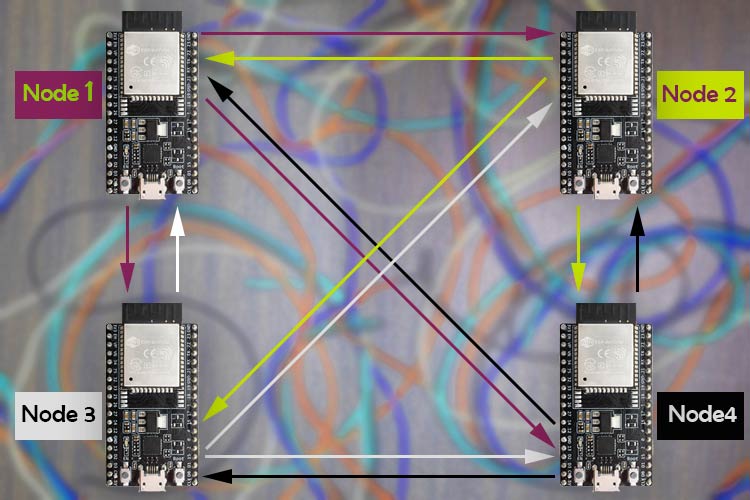
A mesh network is a group of connected devices on a network that is acting as a single network. ESP-Mesh is quite different from a traditional mesh setup. In an ESP-Mesh, the node or a single device can connect to its neighbor simultaneously. One single node can connect to multiple nodes and they can relay data from one node to another. This process is not only efficient but it’s also redundant. If one of any nodes fails; the data from other nodes can reach its destination without a problem. This also opens possibilities of achieving interconnection without needing a central node, which significantly extends the coverage area of the mesh-network. With these features, this network is less prone to conjunction because the total number of nodes in the network is not limited by a single central node.
For the sake of simplicity, we have decided to use four ESP modules; but if you are building this network, you can use as many ESPdevices as you can. To build the mesh network, we are going to use the painlessMesh library for Arduino which has support for both the ESP8266 and the ESP32 modules.
Components Required to build the Mesh Network with ESP
The list of components required for this project is given below. To build this project, I have used components that are pretty generic and you can find them in your local hobby store.
- NodeMCU(ESP8266) - 2
- ESP32 Dev Board - 2
- BMP280 Sensor - 2
- DHT22 Sensor - 1
- DS18B20 Sensor - 1
- Breadboard
- USB Cable (for power and data)
ESP Wi-Fi Mesh - Circuit Diagram
The schematic shown below is used to construct the hardware section for ESP8266 and ESP32 based Wi-Fi Mesh Network.

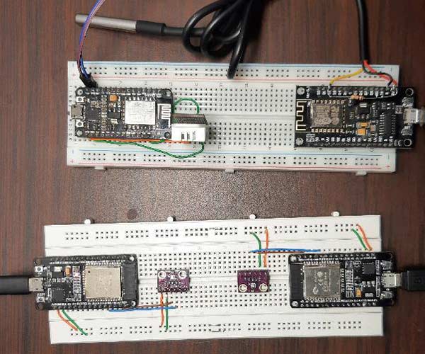
For this circuit, we have connected two BME280 sensors with the ESP32 board, we have connected a DHT22 sensor to one of the ESP8266 board, and we have connected the DS18B20 sensor with another ESP8266 board. We have previously used all these sensors in different projects individually. Here, we will be using them on different NodeMCU/ESP32 boards and then connect them all through an ESP Mesh network. An image for the hardware setup is shown below.
Programming the ESP8266 and ESP32 for Mesh Networking
For this article, we are going to use Arduino IDE to program the ESP32 and the ESP8266 boards. Here, we will use the Painless Mesh library to construct our mesh network. To install the library, go to Sketch->Include Library->Manage Libraries and search for the painlessMesh. Once done, just click install and the library will be installed in the Arduino IDE. As you can see in the image below, once you click Install, this library asks you to install additional dependencies. You need to install those for the library to work.

As you already know from the hardware section, we are going to use a DS18B20 Sensor, A DHT22 sensor, and two BME 280 sensors. We need to install all of those, and it can be simply done with the board manager method.
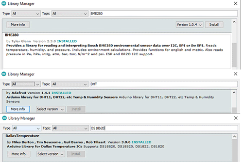
You can also download these libraries from the link given below. Once we have downloaded and installed all the required libraries, we can move on to creating our code.
- Download Painless Mesh Library
- Download DHT Sensor Library
- Download BME280 Library
- Download DallasTemperature Library
Note: The code explanation you see next is the code used in all four boards. We designed the code so that we can tweak it a little and we can upload it to any of our ESP boards despite the fact that it’s an ESP32 or an ESP8266 board.
Upload the Code to ESP32 Board in which a BME280 Sensor is Connected:
As you can see in the hardware schematic, we have connected a BME280 sensor. For that, you need to uncomment the macro for the BME_280 sensor and give it a unique Node Name. In our case, we have used Node_1 and Node_2 for our two ESP32 boards to which we have attached the BME280 sensor
#define BME_280
//#define DHT22
//#define DS18B20
//#define ENABLE_LOG
String nodeName = "NODE_1";
Upload the Code to ESP8266 Board in Which A DHT Sensor is Connected:
In one of our ESP8266 boards, we have a DHT22 sensor and in another one, we have a DS18B20 sensor. To upload the code to the DHT22 board, we have to follow the same process. First, we uncomment the macro for DHT22 and then comment out the macro for BME280 and upload the code to the board to which we have connected the DHT 22 sensor.
//#define BME_280
#define DHT22
//#define DS18B20
//#define ENABLE_LOG
String nodeName = "NODE_3";
Upload the Code to ESP8266 Board in Which A DS18B20 Sensor is Connected:
The process stays exactly the same for this board also. We uncomment the macro for the DS18B20 sensor and we comment on other macros.
//#define BME_280
//#define DHT22
#define DS18B20
//#define ENABLE_LOG
String nodeName = "NODE_3";
Finally, to enable or disable other log statements, you can uncomment the ENABLE_LOG macro. Now that we have an understanding of how the code works, we can move further and explain the code.
We will start our code by including the painlessMesh library and the Arduino_JSON library.
#include <painlessMesh.h>
#include <Arduino_JSON.h>
Next, we define some macros which we will use to enable or disable the parts of our code. This is needed because not all the nodes use the same sensor type and. So for including or excluding parts of our code, we can fit four different codes into a single file.
//#define BME_280
#define DHT22
//#define DS18B20
//#define ENABLE_LOG
Next, we define a String type variable nodeName. This will be used to uniquely identify the nodes in the network. Along with that we also define the float type variable to store the temperature, humidity, and barometric pressure data.
String nodeName = "NODE_4"; // Name needs to be unique
float temp(NAN), hum(NAN), pres(NAN);
From this step onwards, we will be using #ifdef and #endif macros to include or exclude parts of our code. The first section of the code is for the BME280 sensor. As said earlier, we will start by #ifdef BME_280 statement. Next, we define all the required libraries for the BME280 sensor. The BME sensor also uses the wire library, so we define that as well. Next, we make a BME280I2C object bme. Next, using the scope resolution operator, we access the variable of the class and we finish that off with the endif statement.
#ifdef BME_280
#include <BME280I2C.h>
#include <Wire.h>
BME280I2C bme;
BME280::TempUnit tempUnit(BME280::TempUnit_Celsius);
BME280::PresUnit presUnit(BME280::PresUnit_Pa);
#endif
We do the same for the DHT library too. We start with the #ifdef DHT22 statement followed by including the DHT.h library. Next, we define the PIN for DHT, and add a prototype for DHT22. Thereafter, we create an object by passing the above-defined statements. And we finish off with the #endif statement.
#ifdef DHT22
#include "DHT.h"
#define DHTPIN 4
#define DHTTYPE DHT22
DHT dht(DHTPIN, DHTTYPE);
#endif
We also do the same for the DS18B20 sensor. We start with the #ifdef DS18B20 statement.
As the DS18B20 sensor requires OneWire library, we include that along with the DallasTemperature library. Next, we define the pin for the sensor and create an OneWire object by passing the pin variable. Next, we pass the address of the OneWire object to the DallasTemperature object by making a new DallasTemperature object.
#ifdef DS18B20
#include <OneWire.h>
#include <DallasTemperature.h>
const int oneWireBus = 4;
OneWire oneWire(oneWireBus);
DallasTemperature ds18b20(&oneWire);
#endif
Next, we define the Wi-Fi credentials along with the port number. This credential and port number should stay the same for all nodes within the network.
#define   MESH_PREFIX "whateverYouLike"
#define   MESH_PASSWORD "somethingSneaky"
#define   MESH_PORT 5555
Next, we make three instances. One is for the Scheduler, another is for the painlessMesh and the final one is for the JSON library JSONVar
Scheduler userScheduler; // to control your task
painlessMesh  mesh;
JSONVar myVar;
Next, we have created a task that is like a thread that always runs and calls a function after some time. The defined task below will be used to send a broadcast message to all the nodes. The task instantly takes three parameters. First one defines how often the task will call the function, Next, it asks for the life of the task, and finally, it takes a pointer to the calling function.
Task taskSendMessage( TASK_SECOND * 1 , TASK_FOREVER, &sendMessage );
Next, we have our calling function sendMessage(). This function calls another function that returns a string of JSON. As the name implies, the sendMessage task is used to send the message to all the nodes.
void sendMessage() {
  String msg = construnct_json();
  mesh.sendBroadcast( msg );
  taskSendMessage.setInterval( random( TASK_SECOND * 1, TASK_SECOND * 5 ));
}
Next, we have our receivedCallback() function. Whenever a new message arrives, this function gets a call. If you want to do something with the received message, you need to tweak this function to get your job done. This function takes two arguments - the node id and message as a pointer.
void receivedCallback( uint32_t from, String &msg ) {
  Serial.printf("startHere: Received from %u msg=%s\n", from, msg.c_str());
}
Next, we have our newConnectionCallback() function. This function gets a call whenever there is a new device is added to the network, and it sends a print statement to the serial monitor.
void newConnectionCallback(uint32_t nodeId) {
  Serial.printf("--> startHere: New Connection, nodeId = %u\n", nodeId);
}
Next, we have our nodeTimeAdjustedCallback(). This callback function takes care of all the timing necessities required by the painless mesh.
void nodeTimeAdjustedCallback(int32_t offset) {
  Serial.printf("Adjusted time %u. Offset = %d\n", mesh.getNodeTime(), offset);
}
Next, we have our setup() function. In the setup, we initialize the serial and print the node name. This is helpful because once all the nodes are programed, we can identify the nodes easily with the serial monitor. We also have the setDebugMsgTypes( ) class of the mesh object that logs any ERROR | STARTUP messages. Next, we initialize the mesh by-passing the SSID, Password, and Port Number to the init() function. Please keep in mind that these functions also need the pointer to the Scheduler in order to work properly.
Serial.begin(115200);
Serial.println(nodeName);
mesh.setDebugMsgTypes( ERROR | STARTUP );  // set before init() so that you can see startup messages
mesh.init( MESH_PREFIX, MESH_PASSWORD, &userScheduler, MESH_PORT );
Now, we will initialize all the callback functions which we have discussed above. These callback functions will be called whenever a certain task is needed to be performed.
 mesh.onReceive(&receivedCallback);
 mesh.onNewConnection(&newConnectionCallback);
 mesh.onChangedConnections(&changedConnectionCallback);
 mesh.onNodeTimeAdjusted(&nodeTimeAdjustedCallback);
Now we add the task to the task scheduler, and enabled it with the help of the taskSendMessage.enable() method. when it's executed, different tasks start to run simultaneously in the background.
userScheduler.addTask( taskSendMessage );
taskSendMessage.enable();
Next, in the setup section, we have all the necessary ifdef and endif macros which are used to initialize different sensors depending upon the requirement. First, we will config the BME280 sensor. The code below initializes the BME280 sensor and checks for the version of the sensor as the BME280 sensor comes with many different versions.
#ifdef BME_280
  Wire.begin();
  while (!bme.begin())
  {
    Serial.println("Could not find BME280 sensor!");
    delay(1000);
  }
  // bme.chipID(); // Deprecated. See chipModel().
  switch (bme.chipModel())
  {
    case BME280::ChipModel_BME280:
      Serial.println("Found BME280 sensor! Success.");
      break;
    case BME280::ChipModel_BMP280:
      Serial.println("Found BMP280 sensor! No Humidity available.");
      break;
    default:
      Serial.println("Found UNKNOWN sensor! Error!");
  }
#endif
Finally, we have configured the DHT22 and the DS18B20 sensor with the help of the ifdef and #endif method. And this marks the end of the setup() function.
#ifdef DHT22
  Serial.println(F("DHTxx Begin!"));
  dht.begin();
#endif
#ifdef DS18B20
  ds18b20.begin();
  Serial.println(F("DS18B20 Begin!"));
#endif
Next, we have our loop. In this code, the loop dose does not do much, it just updates the mesh with the help of mesh.update() method. It takes care of all the tasks. These tasks will not work if this update method is not present.
void loop()
{
  mesh.update();
  // construnct_json();
}
Next, we have our final function. This function constructs the JSON string and returns it to the calling function. In this function, we start by calling the bme.read() method and we pass all the predefined variables that get updated with new values. Next, we divide the pressure value by 100 because we want to convert it into millibar. Next, we define our JSON array and put the Sensor name, the node name, the temperature, pressure value, and return the values using the JSON.stringify() function. Finally, we define another ifdef and endif macros to enable or disable log parameters.
String construnct_json()
{
#ifdef BME_280
  bme.read(pres, temp, hum, tempUnit, presUnit);
  pres = pres / 100;
  myVar["Sensor Type"] = "BME280";
  myVar["Node Name"] = nodeName;
  myVar["Temperature"] = serialized(String(temp, 2));
  myVar["pres"] = serialized(String(pres, 2));
#ifdef ENABLE_LOG
  Serial.println(JSON.stringify(myVar));
#endif
  return JSON.stringify(myVar);
#endif
Finally, we do the same for the DHT22 and the DS18B20 sensor code.
#ifdef DHT22
  temp = dht.readTemperature();
  hum = dht.readHumidity();
  myVar["Sensor Type"] = "DHT22";
  myVar["Node Name"] = nodeName;
  myVar["Temperature"] = serialized(String(temp));
  myVar["Humidity"] = serialized(String(hum));
#ifdef ENABLE_LOG
  Serial.println(JSON.stringify(myVar));
#endif
  return JSON.stringify(myVar);
#endif
#ifdef DS18B20
  ds18b20.requestTemperatures();
  temp = ds18b20.getTempCByIndex(0);
  myVar["Sensor Type"] = "DS18B20";
  myVar["Node Name"] = nodeName;
  myVar["Temperature"] = serialized(String(temp));
#ifdef ENABLE_LOG
  Serial.println(JSON.stringify(myVar));
#endif
  return JSON.stringify(myVar);
#endif
}
Now, as the coding process is finished; we comment or uncomment the defined macros on top; according to our board which we are going to upload. Next, we give each node a unique name and we simply upload the code. If everything is all right, the code will compile and upload properly without any error.
ESP8266 and ESP32 based Mesh Network - Testing
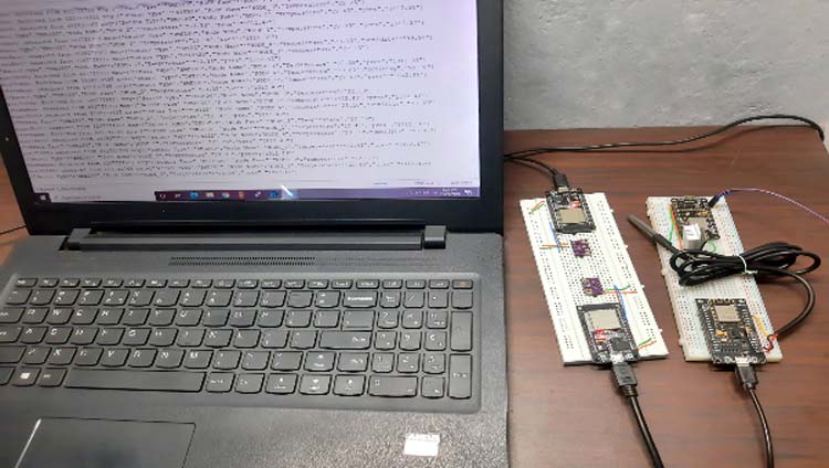
The test setup for the ESp8266 and esp32 based mesh network is shown below. As you can see in the above image, I have connected power to all the esp modules and you can also see the output data on the screen of the laptop. A screenshot of the serial monitor windows is shown below.
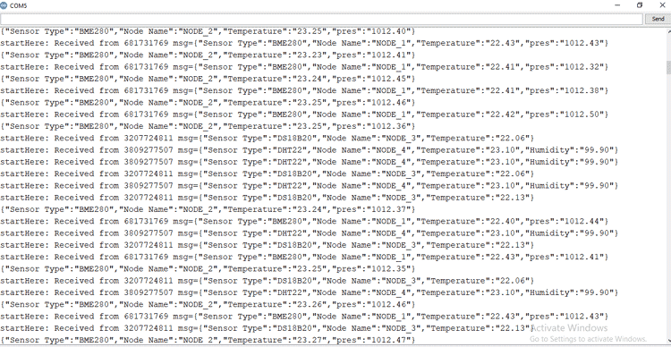
In the above window, you can see that we are easily receiving the data from all four sensors.
The complete working of the project can also be found in the video linked below. Hope you enjoyed the project and found it interesting to build your own. If you have any questions, please leave them in the comment section below. You can also write all your technical questions on forums to get them answered or to start a discussion.
Complete Project Code
#include <painlessMesh.h>
#include <Arduino_JSON.h>
//#define BME_280
#define DHT22
//#define DS18B20
//#define ENABLE_LOG
String nodeName = "NODE_4"; // Name needs to be unique
float temp(NAN), hum(NAN), pres(NAN);
//########################## Init_BME280 ##########################
#ifdef BME_280
#include <BME280I2C.h>
#include <Wire.h>
BME280I2C bme;
BME280::TempUnit tempUnit(BME280::TempUnit_Celsius);
BME280::PresUnit presUnit(BME280::PresUnit_Pa);
#endif
//__________________________ End of _BME280 __________________________
//########################## Init_DHT22 ##########################
#ifdef DHT22
#include "DHT.h"
#define DHTPIN 4
#define DHTTYPE DHT22
DHT dht(DHTPIN, DHTTYPE);
#endif
//__________________________ End of DHT22 __________________________
//########################## Init_Ds18B20 ##########################
#ifdef DS18B20
#include <OneWire.h>
#include <DallasTemperature.h>
const int oneWireBus = 4;
OneWire oneWire(oneWireBus);
DallasTemperature ds18b20(&oneWire);
#endif
//__________________________ End of DHT22 __________________________
#define   MESH_PREFIX     "whateverYouLike"
#define   MESH_PASSWORD   "somethingSneaky"
#define   MESH_PORT       5555
Scheduler userScheduler; // to control your personal task
painlessMesh  mesh;
JSONVar myVar;
void sendMessage() {
  String msg = construnct_json();
  mesh.sendBroadcast( msg );
  taskSendMessage.setInterval( random( TASK_SECOND * 1, TASK_SECOND * 5 ));
}
Task taskSendMessage( TASK_SECOND * 1 , TASK_FOREVER, &sendMessage );
// Needed for painless library
void receivedCallback( uint32_t from, String &msg ) {
  Serial.printf("startHere: Received from %u msg=%s\n", from, msg.c_str());
}
void newConnectionCallback(uint32_t nodeId) {
  Serial.printf("--> startHere: New Connection, nodeId = %u\n", nodeId);
}
void changedConnectionCallback() {
  Serial.printf("Changed connections\n");
}
void nodeTimeAdjustedCallback(int32_t offset) {
  Serial.printf("Adjusted time %u. Offset = %d\n", mesh.getNodeTime(), offset);
}
void setup()
{
  Serial.begin(115200);
  Serial.println(nodeName);
//  mesh.setDebugMsgTypes( ERROR | STARTUP | MESH_STATUS | CONNECTION | SYNC | COMMUNICATION | GENERAL | MSG_TYPES | REMOTE ); // all types on
  mesh.setDebugMsgTypes( ERROR | STARTUP );  // set before init() so that you can see startup messages
  mesh.init( MESH_PREFIX, MESH_PASSWORD, &userScheduler, MESH_PORT );
  mesh.onReceive(&receivedCallback);
  mesh.onNewConnection(&newConnectionCallback);
  mesh.onChangedConnections(&changedConnectionCallback);
  mesh.onNodeTimeAdjusted(&nodeTimeAdjustedCallback);
  userScheduler.addTask( taskSendMessage );
  taskSendMessage.enable();
#ifdef BME_280
  Wire.begin();
  while (!bme.begin())
  {
    Serial.println("Could not find BME280 sensor!");
    delay(1000);
  }
  // bme.chipID(); // Deprecated. See chipModel().
  switch (bme.chipModel())
  {
    case BME280::ChipModel_BME280:
      Serial.println("Found BME280 sensor! Success.");
      break;
    case BME280::ChipModel_BMP280:
      Serial.println("Found BMP280 sensor! No Humidity available.");
      break;
    default:
      Serial.println("Found UNKNOWN sensor! Error!");
  }
#endif
#ifdef DHT22
  Serial.println(F("DHTxx test!"));
  dht.begin();
#endif
#ifdef DS18B20
  ds18b20.begin();
#endif
}
void loop()
{
  mesh.update();
  // construnct_json();
}
String construnct_json()
{
#ifdef BME_280
  bme.read(pres, temp, hum, tempUnit, presUnit); // update with new values
  pres = pres / 100;
  myVar["Sensor Type"] = "BME280";
  myVar["Node Name"] = nodeName;
  myVar["Temperature"] = serialized(String(temp, 2)); // serialized need to conver flot values
  myVar["pres"] = serialized(String(pres, 2));// serialized need to conver flot values
#ifdef ENABLE_LOG
  Serial.println(JSON.stringify(myVar)); //stringify converts the arry to a string
#endif
  return JSON.stringify(myVar);
#endif
#ifdef DHT22
  temp = dht.readTemperature();
  hum = dht.readHumidity();
  myVar["Sensor Type"] = "DHT22";
  myVar["Node Name"] = nodeName;
  myVar["Temperature"] = serialized(String(temp));
  myVar["Humidity"] = serialized(String(hum));
#ifdef ENABLE_LOG
  Serial.println(JSON.stringify(myVar));
#endif
  return JSON.stringify(myVar);
#endif
#ifdef DS18B20
  ds18b20.requestTemperatures();
  temp = ds18b20.getTempCByIndex(0);
  myVar["Sensor Type"] = "DS18B20";
  myVar["Node Name"] = nodeName;
  myVar["Temperature"] = serialized(String(temp));
#ifdef ENABLE_LOG
  Serial.println(JSON.stringify(myVar));
#endif
  return JSON.stringify(myVar);
#endif
}Comments
Hi I'm having a problem in
Hi I'm having a problem in line
taskSendMessage.setInterval( random( TASK_SECOND * 1, TASK_SECOND * 5 ));
Error message: 'taskSendMessage was not declared in this scope.'
I've tried various libraries after using the links from article but to no effect.
I have had another painless mesh working but cannot solve this, pulling my hair out, Can you help please.
Bob
sorry, question redirected to
sorry, question redirected to Forum.
Hello, did you have an answer
Hello, did you have an answer to your question? I have the same problem.
taskSendMessage.setInterval( random( TASK_SECOND * 1, TASK_SECOND * 5 ));
'taskSendMessage' was not declared in this scope
Yours.
Olá , parabéns pelo projeto.
Olá , parabéns pelo projeto. O trabalho foi sintetizado usando apenas o protocolo I2C? Preciso usar o protocolo SPI e não realizar essa transição. Você poderia me dizer como fazer isso?Hello, congratulations on the
Hello, congratulations on the project. Was the work implemented using only the I2C protocol? I need to use the SPI protocol and I cannot implement this transition. Could you tell me how to do this?
Résultats de traduction

Very beautiful and interesting post, I'll try it as soon as possible! It would also be interesting to integrate sleep mode, when the task is not active; and an additional esp for only receiving data from all the others. Thanks and congratulations for the great job