

Digital load scales are another miracle of modern-day engineering and design. Yes, we are talking about the weighing scale we often see in most of the grocery stores and other places, but have you ever wondered how a weight scale work? To answer that question, in this project, we are going to take a look at the load cell and its working. Finally, we will be building a portable Arduino-based load scale with the HX711 Weight Sensor, which can measure weights up to 10kg.
This weighing machine is perfect for local stores, where they pack items in bulk quantity. Like commercial products, our weight scale will have a zero button that zeroes out the scale. Also, It has an option to set weight for measurement, when the measuring weight reaches the set weight, a buzzer beeps fast and stops when the set weight equals the measuring weight. This way, the user can pack it just by hearing the sound and would not have to look at the display. As this is a very simple project, we will be building this very easily using components like Arduino and strain gauge load cell. So, without further delay, let's get right into it.
In a previous article, we have made projects like Raspberry Pi Based Weight Sensor and IoT Smart Container with Email Alert and Web Monitoring using the popular HX711 load cell amplifier module. So, do check that out if that is your requirement.
Arduino Weighing Machine Working
The main component of this project is a Load cell and HX711 load cell amplifier module. As you can see, one side is marked with ten kilograms. Also, you can notice some sort of white protective glue over the load cell and four different colors of wires are coming out, will uncover the secret underneath the white protective glue and the function of these four-color wires later in the article.
A load cell is a transducer that transforms force or pressure into electrical output. It has two sides, let's say the right side and left side, and it's made out of aluminum blocks. As you can see in the middle of the material is thinned by putting a big hole. Which is why that is the point that suffers deformation when a load is placed on the mount side. Now imagine that the right-side cell is mounted to the base and the left side is where the load is placed, this configuration deforms the strain gauge load cell because of the giant hole in the middle.
When a load is placed on the load side of the load cell, the top part will suffer tension, and the bottom part will suffer compression. That is why the aluminum bar bents downward on the left side. If we measure this deformation, we can measure the force that was applied to the aluminum block and that's exactly what we will do.
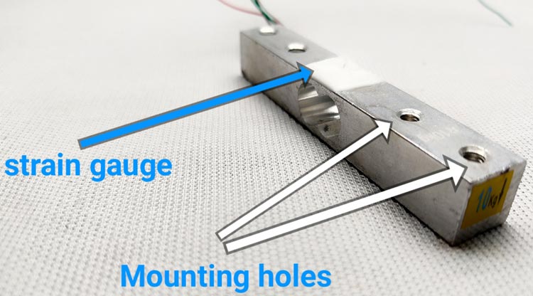
Now, the question remains what's inside the white protective glue? Inside this protective glue, we will find a very thin elastic component which is called a strain gauge. A strain gauge is a component that is used to measure strain. If we take a closer look at this component, we can see two connection pads, and then we have a conductive wire pattern with repetitive deflections. This conductive wire has a defined resistance. When we bend it, the resistance value will change? So, one side of the strain gauge is mounted and fixed in a place, if we place a weight on the other side of the aluminum bar, this will force the strain gauge to bend, which will cause a change in resistance. How this happens actually? The conductive pattern of the strain gauge is made out of copper, this wire will have a certain area and length, so these two units will give the resistance of the wire. The resistance of a wire opposes the flow of current. Now it's obvious that if the area of this wire gets smaller, fewer electrons could pass meaning a lower current. Now if we increase the area, it will increase the resistance of a conductor. If some force is applied to this wire, this will stretch the area and it will get smaller at the same time, resistance increases. But this resistance variation is very low. If we stretch the strain gauge, the resistance will increase and if we compress it, the resistance will get lower. To measure the force, we need to measure the resistance. Measuring the resistance directly is not always practical, because the change is very small. So instead of measuring resistance, we can measure voltages easily. So, in this case, we need to convert the gauge output from resistance values to voltage values.
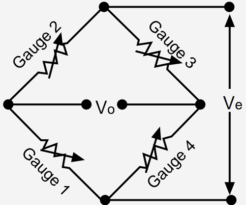
We can do this with help of the Wheatstone bridge. We place the strain gauge in the Wheatstone bridge if the bridge is balanced, the voltage in the middle point should be zero (previously we have built a project where we have described how a Wheatstone bridge works, you can check that out if you want to know more about the topic). When the strain gauge changes its resistance, it will unbalance the bridge, and the voltage will also change. So, this is how the Wheatstone bridge converts resistance variations to voltage values.
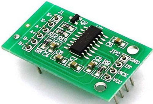
But this voltage change is still very small, so to increase that, we need to use the HX711 module. HX711 is a 24-bit Differential ADC, in this way, we could measure very small voltage changes. it will give values from 0 to 2 exponential 24.
Components Required for Arduino Based Weighing Machine
To make this project as simple as possible, we have used very generic components that you can find in any local hobby store. The image below will give you an idea about the components. Furthermore, we have the Bill of Materials (BOM) listed below.
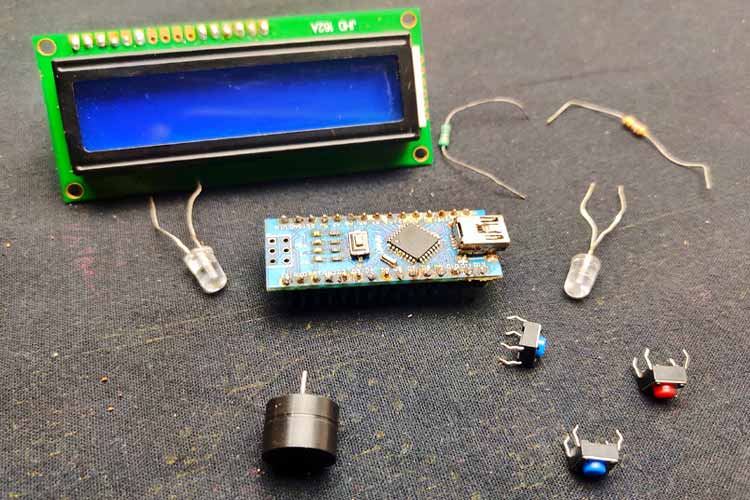
- Load cell (We are using a 10 kg load cell)
- HX 711 amplifier module
- Arduino Nano
- I2C LCD 16X2 – I2C Compatible
- 1k resistor -2 Nos
- LEDs -2Nos
- Buzzer
- Common PCB
- 7.4V battery (if you want it portable)
- LM7805 voltage regulator
Arduino Based Weighing Machine - Circuit Diagram

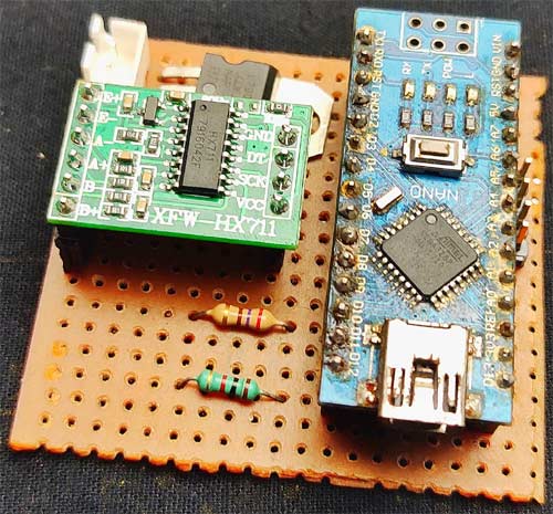
The load cell has four wires which are red, black, green, and white. This color may vary according to the manufacturers, so it's better to refer to the datasheet. Connect red to E+ of HX711 board, connect black to E-, connect white to A+, and connect green to A-, Dout, and clock of the board connect to D4 and D5 respectively. Connect one end of push buttons to D3, D8, D9, and other ends to the ground. We have I2C LCD, so connect SDA to A4 and SCL to A5. Connect the ground of LCD, HX711, and Arduino to the ground, also connect VCCs to the 5Vpin of Arduino. All the modules work on 5V, so we have added an LM7805 voltage regulator. If you don't want it as portable, you can directly power the Arduino using a USB cable.
Making the Circuit on a Dotted Perfboard
We have soldered all the components on a common dotted perfboard. We used female headers to solder the Arduino and ADC with the circuit board, also we have used wires to connect all the pushbuttons and LEDs. After all the soldering process is finished, we have made sure that proper 5V is coming out of the LM7805. Finally, we have put a switch to power on/off the circuit. Once we were all finished, it looked like the image below.
Building an Enclosure for Arduino Based Weighing Machine
As you can see, the load cell has some screw threads, so we could mount it on a base plate. We will be using a PVC board for the base of our scale, for that, we first cut 20*20 cm square and four 20*5 rectangles from the PVC board. Then using hard glue, we glued every piece and made a small enclosure.
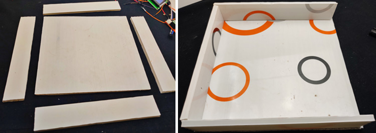
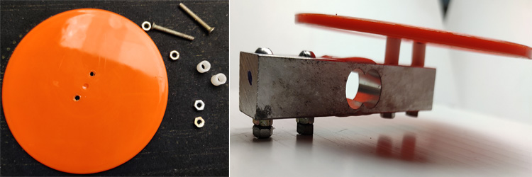
Remember, we didn't fix one side, because we need to place the pushbuttons, LEDs, and the LCD on it. Then we used a plastic board for the top of the scale. Before making this setup permanent, we need to make sure that we have sufficient space from the ground to the load cell, so it will be able to bend, so we placed screw and nuts in between the load cell and the base, also we added some plastic spacers in between the load cell and top part. we used a round plastic sheet as the top smart of balance.
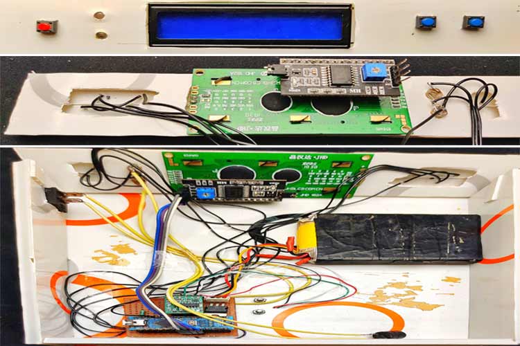
Then we placed the LCD, LEDs, and push-buttons to the front panel, and everything connected with long insulated wire. After we finished the wiring process, we glued the front panel to the main base with some inclination, so we can read the values from LCD very easily. finally, we attached the main switch to the side of the balance and that's it. This is how we made the body for our weight scale.
You can design with your ideas but remember to place the load cell-like as in the image.

Arduino Weighing Machine - Code
As we are now finished with the build process for our digital scale, we can move onto the programming part. For easy programming, we are going to use the HX711 library, EEPROM Library, and the LiquidCrystal library. You can download the HX711 library from the official GitHub repository, or go to tools > include library > manage library, then search library using keyword HX711, after downloading the library, Install it into Arduino ide.
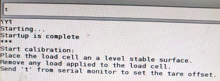
First, we need to calibrate the load cell and store that value on EEPROM, for that, go to file > examples > HX 711_ADC, then select the calibration code. Before uploading the code, place the balance on a stable plane surface. Then upload the code to Arduino and open the serial monitor. Then change the baud rate to 572600. Now monitor ask to take the weight, for that we need to press t and enter.
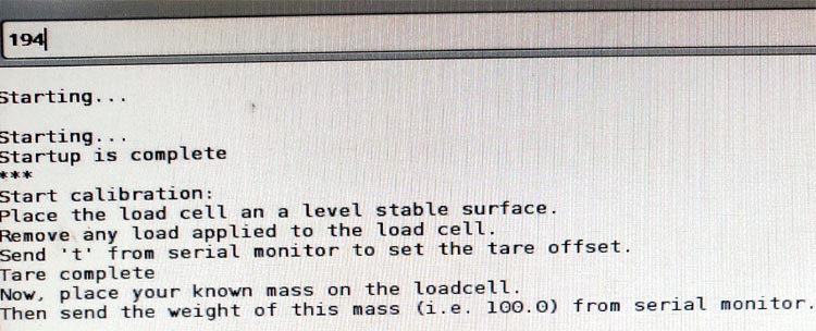
Now, we need to place the known weight on the balance, in my case, that is 194gm. After placing the known weight, type weight on the serial monitor, and hit enter.
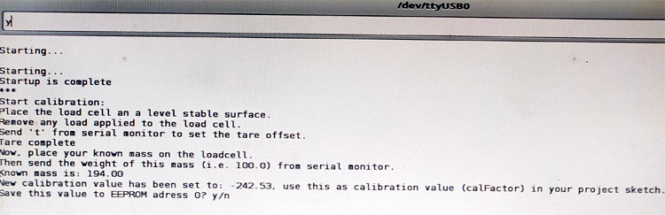
Now, the serial monitor asks you whether you want to save the value in EEPROM or not, so type Y for choosing yes. Now we can see the weight on the serial monitor.
The main code of this project, which we developed from the example sketch of the HX711 library. You can download the code of this project from below.
In the coding section, first, we added all three libraries. The HX711 library is for taking the load cell values. EEPROM is the inbuilt library of Arduino ide, which is used to store values in EEPROM and the LiquidCrystal library is for the l2C LCD Module.
#include <HX711_ADC.h>
#include <EEPROM.h>
#include <LiquidCrystal_I2C.h>
Then defined integers for different pins and assigned values. HX711_ADC loadcell function is for setting the Dout and clock pin.
const int HX711_dout = 4;
const int HX711_sck = 5;
int tpin = 3;
HX711_ADC LoadCell(HX711_dout, HX711_sck);
const int calVal_eepromAdress = 0;
long t;
const int  Up_buttonPin   = 9;
const int  Down_buttonPin = 8;
float buttonPushCounter = 0;
float up_buttonState = 0;
float up_lastButtonState = 0;
float down_buttonState = 0;
float down_lastButtonState = 0;
In the setup section, first, we started the serial monitor, this is just for debugging only. Then we defined the pin modes, all push buttons are defined as input. With help of the Arduino PULL UP function, we set the pins to a logical high at normally. So, we don't want to use any external resistors for that.
  pinMode(tpin, INPUT_PULLUP);
  pinMode(6, OUTPUT);
  pinMode(12, OUTPUT);
  pinMode( Up_buttonPin , INPUT_PULLUP);
  pinMode( Down_buttonPin , INPUT_PULLUP);
The following lines of code are for setting I2C LCD. First, we displayed the welcome text using the LCD.print() function, after two seconds, we cleared the display using lcd.clear(). That is, in the beginning, the display shows ARDUINO BALANCE as welcome text, and after two seconds, it will clear and display the measuring weights.
  lcd.init();
  lcd.backlight();
  lcd.setCursor(0, 0);
  lcd.print("ARDUINO BALANCE");
  lcd.setCursor(0, 1);
  lcd.print("let's measure");
  delay(2000);
  lcd.clear();
Then started to read the values from loadcell using loadCell.begin() function, after that, we read the EEPROM for the calibrated values, we do that by using the EEPROM.get() function. That is, we already stored the value using calibration sketch in the EEPROM address, we just retake that value.
  LoadCell.begin();
 EEPROM.get(calVal_eepromAdress, calibrationValue);
In the loop section, first, we check if any data from the load cell is available using LoadCell.update(), if available, we read and store that data, for that, we are using LoadCell.getData(). Next, we need to display the stored value in LCD. To do that, we used the LCD.print() function. also, we print the set weight. Set weight is setting with the help of the Pushbutton counter. That explained in the last section.
 if (LoadCell.update()) newDataReady = true;
if (newDataReady)
  {
    if (millis() > t + serialPrintInterval) {
      float i = LoadCell.getData();
      lcd.setCursor(0, 0);
      lcd.print("set wei:");
      lcd.setCursor(9, 0);
      lcd.print(buttonPushCounter);
      lcd.setCursor(14, 0);
      lcd.print("GM");
      lcd.setCursor(0, 1);
      lcd.print("weight :");
      lcd.setCursor(9, 1);
      lcd.print(i);
      lcd.setCursor(14, 1);
      lcd.print("GM");
Next, we set the tare value, for that, first, we read the state of the tare pushbutton using the digitalRead() function, if the state is low, we tare that weight to zero. Tare function of this weight scale is to bring the readings to zero. For example, if we have a bowl in which the things are loaded, then the net weight will be the weight of the bowl + the weight of the things. If we press the tare button with the bowl on the load cell before loading things, the weight of the basket will be negated and we can measure the weight of the things alone.
if (digitalRead(tpin) == LOW) {
LoadCell.tareNoDelay();
Now, we need to set the conditions for different indications like setting the delay of the buzzer and the led status. We did that using if conditions, we have a total of three conditions. First, we calculate the difference between set weight and measuring weight, then stored that value in the variable k.
float k = buttonPushCounter-i ;
1. If the difference between set weight and measuring weight is greater than or equal to 50gms, the buzzer beeps with a 200-millisecond delay (slowly).
   if ( k >= 50 )
  {
    digitalWrite (6, HIGH);
    delay(200);
    digitalWrite (6, LOW);
    delay(200);
  }
2. If the difference between set weight and measuring weight is lower than 50 and greater than 1 gram, the buzzer beeps with a 50-millisecond delay (faster).
  if ( k < 50 && k > 1 )
  {
    digitalWrite (6, HIGH);
    delay(50);
    digitalWrite (6, LOW);
    delay(50);
  }
3. When the measuring weight equals or greater than the set value, this will turn on the green led and off the buzzer and red led.
 if(i>=buttonPushCounter)
  {
    digitalWrite (6, LOW);
    digitalWrite (12, HIGH);
      }
We have two more void functions () for setting the set weight (for counting the button press).
The function increasing the set value by 10gms for each press. This is done by using the digitalRead function of Arduino if the pin is low that means the button is pressed and that will increment the value by 10gms.
up_buttonState = digitalRead(Up_buttonPin);
 if (up_buttonState != up_lastButtonState) {
if (up_buttonState == LOW) {
 bPress = true;
 buttonPushCounter = buttonPushCounter + 10;
}
Similarly,
checkdown is for decreasing the set value by 10gms for each press.
down_buttonState = digitalRead(Down_buttonPin);
  if (down_buttonState != down_lastButtonState) {
 if (down_buttonState == LOW) {
 bPress = true;
 buttonPushCounter = buttonPushCounter - 10;
}
This marks the end of the programming part.
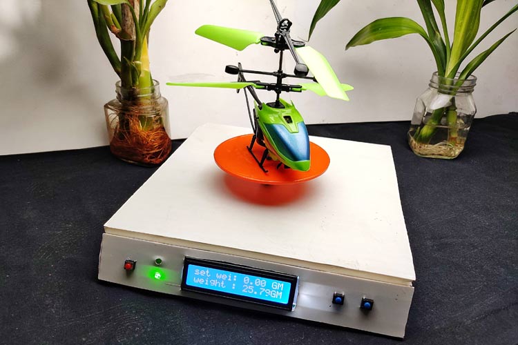
This Arduino based electronic scale is perfect for measuring the weights up to 10kg (we can increase this limit by using a higher rated loadcell). This is 99% accurate to original measurements.
If you have any questions regarding this Arduino based LCD weight balance machine circuit, please post it in the comment section, thank you!
Complete Project Code
#include <HX711_ADC.h>
#include <EEPROM.h>
#include <LiquidCrystal_I2C.h>
LiquidCrystal_I2C lcd(0x27, 2, 16);
HX711_ADC LoadCell(HX711_dout, HX711_sck);
const int HX711_dout = 4; //mcu > HX711 dout pin
const int HX711_sck = 5; //mcu > HX711 sck pin
int tpin = 3;
const int calVal_eepromAdress = 0;
long t;
const int  Up_buttonPin   = 9;    // the pin that the pushbutton is attached to
const int  Down_buttonPin = 8;
float buttonPushCounter = 0;   // counter for the number of button presses
float up_buttonState = 0;         // current state of the up button
float up_lastButtonState = 0;     // previous state of the up button
float down_buttonState = 0;         // current state of the up button
float down_lastButtonState = 0;     // previous state of the up button
bool bPress = false;
void setup() {
  Serial.begin(57600);
  delay(10);
  Serial.println();
  Serial.println("Starting...");
  pinMode(tpin, INPUT_PULLUP);
  pinMode(6, OUTPUT);
  pinMode(12, OUTPUT);
  pinMode( Up_buttonPin , INPUT_PULLUP);
  pinMode( Down_buttonPin , INPUT_PULLUP);
  lcd.init();
  lcd.backlight();
  lcd.setCursor(0, 0);
  lcd.print("ARDUINO BALANCE");
  lcd.setCursor(0, 1);
  lcd.print("let's measure");
  delay(2000);
  lcd.clear();
  LoadCell.begin();
  float calibrationValue; // calibration value (see example file "Calibration.ino")
  calibrationValue = 696.0; // uncomment this if you want to set the calibration value in the sketch
#if defined(ESP8266)|| defined(ESP32)
  //EEPROM.begin(512); // uncomment this if you use ESP8266/ESP32 and want to fetch the calibration value from eeprom
#endif
  EEPROM.get(calVal_eepromAdress, calibrationValue); // uncomment this if you want to fetch the calibration value from eeprom
  long stabilizingtime = 2000; // preciscion right after power-up can be improved by adding a few seconds of stabilizing time
  boolean _tare = true; //set this to false if you don't want tare to be performed in the next step
  LoadCell.start(stabilizingtime, _tare);
  if (LoadCell.getTareTimeoutFlag())
  {
    Serial.println("Timeout, check MCU>HX711 wiring and pin designations");
    while (1);
  }
  else
  {
    LoadCell.setCalFactor(calibrationValue); // set calibration value (float)
    Serial.println("Startup is complete");
  }
}
void loop() {
  static boolean newDataReady = 0;
  const int serialPrintInterval = 0; //increase value to slow down serial print activity
  // check for new data/start next conversion:
  if (LoadCell.update()) newDataReady = true;
  // get smoothed value from the dataset:
  if (newDataReady)
  {
    if (millis() > t + serialPrintInterval) {
      float i = LoadCell.getData();
      Serial.print("Load_cell output val: ");
      Serial.println(i);
      newDataReady = 0;
      t = millis();
      lcd.setCursor(0, 0);
      lcd.print("set wei:");
      lcd.setCursor(9, 0);
      lcd.print(buttonPushCounter);
      lcd.setCursor(14, 0);
      lcd.print("GM");
      lcd.setCursor(0, 1);
      lcd.print("weight :");
      lcd.setCursor(9, 1);
      lcd.print(i);
      lcd.setCursor(14, 1);
      lcd.print("GM");
    }
  }
  checkUp();
  checkDown();
  if (digitalRead(tpin) == LOW) {
    LoadCell.tareNoDelay();
  }
  // check if last tare operation is complete:
  if (LoadCell.getTareStatus() == true) {
    lcd.clear();
    lcd.print("Tare complete");
    delay(1000);
    lcd.clear();
  }
  float i = LoadCell.getData();
  float k = buttonPushCounter - i;
  if ( k < 50 && k > 1 )
  {
    digitalWrite (6, HIGH);
    delay(50);
    digitalWrite (6, LOW);
    delay(50);
  }
  if ( k >= 50 )
  {
    digitalWrite (6, HIGH);
    delay(200);
    digitalWrite (6, LOW);
    delay(200);
  }
  if (i >= buttonPushCounter)
  {
    digitalWrite (6, LOW);
    digitalWrite (12, HIGH);
  }
  else
  {
    digitalWrite(12, LOW);
  }
}
void checkUp()
{
  up_buttonState = digitalRead(Up_buttonPin);
  // compare the buttonState to its previous state
  if (up_buttonState != up_lastButtonState)
  {
    // if the state has changed, increment the counter
    if (up_buttonState == LOW)
    {
      bPress = true;
      // if the current state is HIGH then the button went from off to on:
      buttonPushCounter = buttonPushCounter + 10;
    }
  }
  // save the current state as the last state, for next time through the loop
  up_lastButtonState = up_buttonState;
}
void checkDown()
{
  down_buttonState = digitalRead(Down_buttonPin);
  // compare the buttonState to its previous state
  if (down_buttonState != down_lastButtonState)
  {
    // if the state has changed, increment the counter
    if (down_buttonState == LOW)
    {
      bPress = true;
      buttonPushCounter = buttonPushCounter - 10;
    }
  }
  // save the current state as the last state, for next time through the loop
  down_lastButtonState = down_buttonState;
}Comments
Thanks, this is almost exactly what I wa slookiing for! Can you just give me a pointer on where in the code I should alter to make the LCD/Arduino do the following?
1. Accept selection of a "starting weight" (going to be a selection of 750 or 1000 g)
2. Calculate the "tare value" according to the initial measurement (e.g., if the selection in 1 is 750 and the initial weight is 767, then the tare value will be 17)
3. Constantly display "current weight" (measured weight - tare value) / "starting weight" as well as that proportion in % (curren/starting * 100)
Thanks!
nice work bro.. but am having issue in compiling the code on the following header line..
HX711_ADC LoadCell(HX711_dout, HX711_sck);
the error message is "'HX711_dout' was not declared in this scope"
pls i need your help
thanks
I've ran into the same problem.
There is an error in the code.
Just put the line:
HX711_ADC LoadCell(HX711_dout, HX711_sck);
below (and not before)
the lines:
const int HX711_dout = 4; //mcu > HX711 dout pin
const int HX711_sck = 5; //mcu > HX711 sck pin
So this should be the correct order:

const int HX711_dout = 4; //mcu > HX711 dout pin
const int HX711_sck = 5; //mcu > HX711 sck pin
HX711_ADC LoadCell(HX711_dout, HX711_sck);
HX711_ADC LoadCell(HX711_dout, HX711_sck);
the error message is "'HX711_dout' was not declared in this scope"
pls i need your help
thanks
prashant singh
NICE BRO.,BUT LIAD CELL...ERROE...PLS UPDATE
I'm just starting with this interesting project.
I've already discovered a little flaw in the circuit diagram: ☺
The GND AND the VCC of the HX711 module are both connected to GND.
VCC should be wired to +5V.
If anyone (?) is interested:
I've changed the code a bit. Modified some parameters. Made sure the values are properly aligned on the display (added a bit of code for that).
Anyone reading this????
show me am interested
I am interested, in the comment below, my suggestions. I am interested, in the comment below, my suggestions.I was just looking for something like this.
I am interested in developing this project.
I am interested in the possibility of controlling a stepper motor (in parallel with a relay - e.g. by an enable signal).
I am ready to update the schematic in KicKad, design a single-sided PCB, add a panel casing in FreeCad (for 3D printing).
In my opinion, you would need to add buttons: turning on the relay (or stepper motor) and if you would add a button for resetting (a counter of weights).
The speed of the stepper motor could be adjusted with a potentiometer on the back of the housing.
Unfortunately, I'm not very good at programming, is there anyone willing to cooperate?Hello,
I am facing a problem with this project
The weight or the output value is saying "nan"
I am using a 180kg load cell
Can you help me please?
thank you in advance!
Hi Rajesh
I love this uncomplicated but accurate scale and I have build the demo version on the breadboard, One question! is it possible to incorporate a relay to switch on and off with the set weight and a stop start button to begin the weighing and stop at preset weight?
I would appreciate some feedback on this
thank you
Yes, you can with code modification.

hellow your work is nice. please make a projetc that control a setper motor with temperature .