In previous tutorials, we have learned about How to interface GPS module with Computer and how to Track vehicle using GSM and GPS. We also built Vehicle Accident Alert System using Arduino and accelerometer. Here we are again building the same project but this time a MSP430 launchpad and a vibration sensor will be used to detect vehicle accident. So this project will also tell about interfacing a vibration sensor with MSP430 launchpad. You can find more MSP430 projects here.
Here Vibration sensor module detects the vibration of vehicle and sends a signal to MSP430 Launchpad. Then MSP430 fetches data from GPS module and send it to user Mobile Phone via SMS using GSM module. An LED will also glow as Accident Alert signal, this LED can be replaced by some alarm. Location of the accident is sent in the form of Google Map link, derived from the latitude and longitude from the GPS module. See the Demo Video at the end.
Components Required
- MSP430 Launchpad
- SIM900 GSM Module
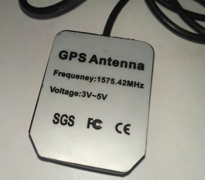
- Ublox NEO-6M GPS Module
- Vibration sensor module
- 16x2 LCD
- Power Supply
- Connecting Wires
- 10 K-POT
- Breadboard or PCB
- Power supply 12v 1amp
- 3.3v Power supply
- 5v power supply
Before going into Project, we will discuss GPS, GSM and Vibration Sensor. Also if you are new to MSP430 then start with LED blink using MSP430 Tutorial.
GPS Module and Its Working:
GPS stands for Global Positioning System and used to detect the Latitude and Longitude of any location on the Earth, with exact UTC time (Universal Time Coordinated). GPS module is used to track the location of accident in our project. This device receives the coordinates from the satellite for each and every second, with time and date. We have previously extracted $GPGGA string in Vehicle Tracking System to find the Latitude and Longitude Coordinates.
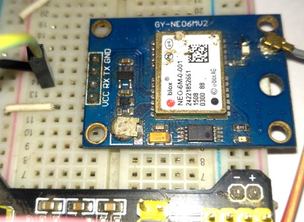
GPS module sends the data related to tracking position in real time, and it sends so many data in NMEA format (see the screenshot below). NMEA format consists several sentences, in which we only need one sentence. This sentence starts from $GPGGA and contains the coordinates, time and other useful information. This GPGGA is referred to Global Positioning System Fix Data. Know more about NMEA sentences and reading GPS data here.
We can extract coordinate from $GPGGA string by counting the commas in the string. Suppose you find $GPGGA string and stores it in an array, then Latitude can be found after two commas and Longitude can be found after four commas. Now, this latitude and longitude can be put in other arrays.
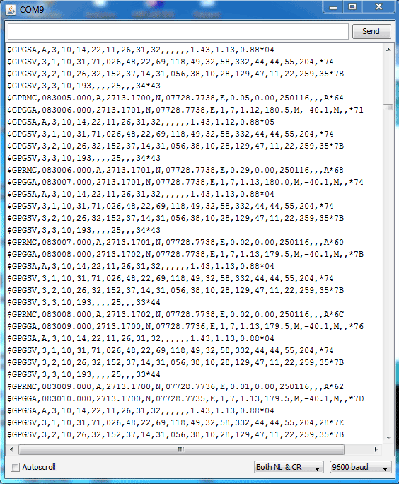
Below is the $GPGGA String, along with its description:
$GPGGA,104534.000,7791.0381,N,06727.4434,E,1,08,0.9,510.4,M,43.9,M,,*47
$GPGGA,HHMMSS.SSS,latitude,N,longitude,E,FQ,NOS,HDP,altitude,M,height,M,,checksum data
|
Identifier |
Description |
|
$GPGGA |
Global Positioning system fix data |
|
HHMMSS.SSS |
Time in hour minute seconds and milliseconds format. |
|
Latitude |
Latitude (Coordinate) |
|
N |
Direction N=North, S=South |
|
Longitude |
Longitude(Coordinate) |
|
E |
Direction E= East, W=West |
|
FQ |
Fix Quality Data |
|
NOS |
No. of Satellites being Used |
|
HDP |
Horizontal Dilution of Precision |
|
Altitude |
Altitude (meters above from sea level) |
|
M |
Meter |
|
Height |
Height |
|
Checksum |
Checksum Data |
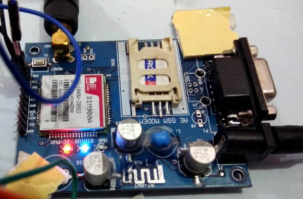
GSM Module
The SIM900 is a complete Quad-band GSM/GPRS Module which can be embedded easily used by customer or hobbyist. SIM900 GSM Module provides an industry-standard interface. SIM900 delivers GSM/GPRS 850/900/1800/1900MHz performance for voice, SMS, Data with low power consumption. It is easily available in the market.
- SIM900 designed by using single-chip processor integrating AMR926EJ-S core
- Quad-band GSM/GPRS module in small size.
- GPRS Enabled
AT Commands
AT means ATTENTION. This command is used to control the GSM module. There are some commands for calling and messaging that we have used in many of our previous GSM projects with Arduino. For testing GSM Module we used AT command. After receiving AT Command GSM Module respond with OK. It means GSM module is working fine. Below is some AT commands we used here in this project:
ATE0 For echo off
AT+CNMI=2,2,0,0,0 <ENTER> Auto opened message Receiving. (No need to open message)
ATD<Mobile Number>; <ENTER> making a call (ATD+919610126059;\r\n)
AT+CMGF=1 <ENTER> Selecting Text mode
AT+CMGS=”Mobile Number” <ENTER> Assigning recipient’s mobile number
>>Now we can write our message
>>After writing a message
Ctrl+Z sends message command (26 in decimal).
ENTER=0x0d in HEX
(To learn more about GSM module, Check our various GSM projects with various microcontrollers here)
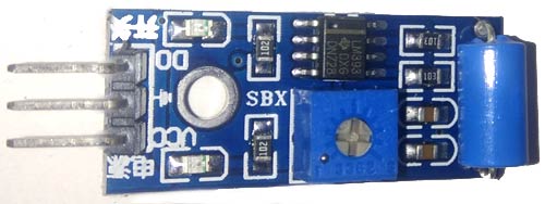
Vibration Sensor Module
In this MSP430 Accident Alert System project, we have used a vibration sensor module which detects vibrations or sudden modulations. Vibration sensor module gives a digital output HIGH/LOW logic depending on the module. In our case, we have used an active HIGH logic vibration sensor module. It means whenever the vibration sensor will detect vibration it will give HIGH logic to the microcontroller.

Circuit Explanation
Circuit Connections of this Vehicle Accident Alert System Project is simple. Here Tx pin of GPS module is directly connected to digital pin number P1_1 of MSP430 Launchpad (hardware Serial) and 5v is used to power GPS Module. By using Software Serial Library here, we have allowed serial communication on pin P_6 and P1_7, and made them Rx and Tx respectively and connected to the GSM module. 12 Volt supply is used to power the GSM Module. The vibration sensor is connected at P1_3. A LED is also used for indicate the accident detection. Rest of connections are shown in the circuit diagram.
![]()
![]()
Programming Explanation
Programming for this project is easy except the GPS part. Complete code is given at the end of the project. To write or compile the code in MSP430 we have used Energia IDE which is Arduino compatible. Most of Arduino IDE function can be used directly in this Energia IDE.
So first of all we have included a required libraries and declared pin and variables.
#include <SoftwareSerial.h>
SoftwareSerial GSM(P1_6, P1_7); // RX, TX

float latitude=0;
float logitude=0;

#define led P1_0
const int vibrationSensor=PUSH2;
int i=0;
Given function is used for reading vibration sensor signal. This function will filter small or false vibrations as well.
#define count_max 25
char SensorRead(int pin)   // read sw with debounce
{
   char count_low=0,count_high = 0;
   do
  {
    delay(1);
    if (digitalRead(pin) == HIGH)
    {
     count_high++;
     count_low = 0;
    }

    else
    {
       count_high = 0;
       count_low++;
    }
  }while(count_low< count_max && count_high < count_max);

  if (count_low >= count_max)
  return LOW;
  else
  return HIGH;
}
Below function detects vibration and call gpsEvent() function to get GPS coordinate and finally call the Send() function to send SMS.
void loop()
{
    if(SensorRead(vibrationSensor) == HIGH)
    {
        digitalWrite(led, HIGH);
        gpsEvent();
        Send();
        digitalWrite(led, LOW);
        delay(2000);
    }
}
Given Function is responsible for getting GPS strings from GPS module, extract the coordinates from them and convert them in degree-decimal format.
void gpsEvent()
{
  char gpsString[55];
  char test[]="RMC";
  i=0;
  while(1)
  {
   while (Serial.available())            //Serial incomming data from GPS
   {
    char inChar = (char)Serial.read();
     gpsString[i]=inChar;                    //store incomming data from GPS to temparary string str[]
     i++;
     if (i < 4)
     {
      if(gpsString[i-1] != test[i-1])         //check for right string
        i=0;
     }
int degree=0;
       degree=gpsString[16]-48;
       degree*=10;
       degree+=gpsString[17]-48;
       int minut_int=0;
       minut_int=gpsString[18]-48;
       minut_int*=10;
       minut_int+=gpsString[19]-48;

       int minut_dec=0;
       minut_dec+= (gpsString[21]-48)*10000;
       minut_dec+= (gpsString[22]-48)*1000;
       minut_dec+= (gpsString[23]-48)*100;
       minut_dec+= (gpsString[24]-48)*10;
       minut_dec+= (gpsString[25]-48);

       float minut= ((float)minut_int + ((float)minut_dec/100000.0))/60.0;
       latitude= ((float)degree + minut);
And finally, Send() function is used to send the SMS to the user number that is inserted in this part of the code.
void Send()
{
   GSM.print("AT+CMGS=");
   GSM.print('"');
   GSM.print("961****059"); // enter your Mobile number
   GSM.println('"');
   delay(500);
  // GSM.print("Latitude:");
  // GSM.println(latitude);
   GSM.println("Accident Happned");
   delay(500);
  // GSM.print(" longitude:");
  // GSM.println(logitude);
   GSM.println("Click On link to see Location");
   GSM.print("http://maps.google.com/maps?&z=15&mrt=yp&t=k&q=");
   GSM.print(latitude,6);
   GSM.print("+");
   GSM.print(logitude,6);
   GSM.write(26);
   delay(4000);
}
Complete code and demo video is given below, you can check all the functions in the code.
Complete Project Code
#include <SoftwareSerial.h>
SoftwareSerial GSM(P1_6, P1_7); // RX, TX

float latitude=0;
float logitude=0;

#define led P1_0
const int vibrationSensor=PUSH2;
int i=0;

#define count_max 25
char SensorRead(int pin)   // read sw with debounce
{
   char count_low=0,count_high = 0;
   do
  {
    delay(1);
    if (digitalRead(pin) == HIGH)
    {
count_high++;
count_low = 0;
    }
    else
    {
       count_high = 0;
       count_low++;
    }
  }while(count_low< count_max && count_high < count_max);

  if (count_low >= count_max)
  return LOW;
  else
  return HIGH;
}

void setup()
{
  GSM.begin(9600);
  Serial.begin(9600);
  GSM.println("AT");
  delay(1000);
  GSM.println("ATE0");
  delay(1000);
  GSM.println("AT+CMGF=1");
  pinMode(led , OUTPUT);
  digitalWrite(led, LOW);
  pinMode(vibrationSensor, INPUT_PULLUP);
}

void loop()
{
    if(SensorRead(vibrationSensor) == HIGH)
    {
        digitalWrite(led, HIGH);
        gpsEvent();
        Send();
        digitalWrite(led, LOW);
        delay(2000);
    }
}

void gpsEvent()
{
  char gpsString[55];
  char test[]="RMC";
  i=0;
  while(1)
  {
   while (Serial.available())            //Serial incomming data from GPS
   {
    char inChar = (char)Serial.read();
     gpsString[i]=inChar;                    //store incomming data from GPS to temparary string str[]
     i++;
     if (i < 4)
     {
      if(gpsString[i-1] != test[i-1])         //check for right string
        i=0;
     }
     if(i>50)
     {
       int degree=0;
       degree=gpsString[16]-48;
       degree*=10;
       degree+=gpsString[17]-48;
       int minut_int=0;
       minut_int=gpsString[18]-48;
       minut_int*=10;
       minut_int+=gpsString[19]-48;

       int minut_dec=0;
       minut_dec+= (gpsString[21]-48)*10000;
       minut_dec+= (gpsString[22]-48)*1000;
       minut_dec+= (gpsString[23]-48)*100;
       minut_dec+= (gpsString[24]-48)*10;
       minut_dec+= (gpsString[25]-48);

       float minut= ((float)minut_int + ((float)minut_dec/100000.0))/60.0;
       latitude= ((float)degree + minut);

       degree=0;
       degree=gpsString[30]-48;
       degree*=10;
       degree+=gpsString[31]-48;

       minut_int=0;
       minut_int=gpsString[32]-48;
       minut_int*=10;
       minut_int+=gpsString[33]-48;

       minut_dec=0;
       minut_dec+= (gpsString[35]-48)*10000;
       minut_dec+= (gpsString[36]-48)*1000;
       minut_dec+= (gpsString[37]-48)*100;
       minut_dec+= (gpsString[38]-48)*10;
       minut_dec+= (gpsString[39]-48);

       minut= ((float)minut_int + ((float)minut_dec/100000.0))/60.0;
       logitude= ((float)degree + minut);
       i=0;
       Serial.flush();
       return;
     }
  }
  }
}

void Send()
{
   GSM.print("AT+CMGS=");
   GSM.print('"');
   GSM.print("961****059"); // enter your Mobile number
   GSM.println('"');
   delay(500);
  // GSM.print("Latitude:");
  // GSM.println(latitude);
   GSM.println("Accident Happned");
   delay(500);
  // GSM.print(" longitude:");
  // GSM.println(logitude);
   GSM.println("Click On link to see Location");
   GSM.print("http://maps.google.com/maps?&z=15&mrt=yp&t=k&q=");
   GSM.print(latitude,6);
   GSM.print("+");
   GSM.print(logitude,6);
   GSM.write(26);
   delay(4000);
}
Comments
Could you leave your facebook
Could you leave your facebook or gmail? We can discuss easily by using it
converting Launchpad wiring to Arduino
Hi SIR,
I'm doing this type of project in arduino. Mine is alcohol detection, and the location is sent using GPS and GSM.
can you please help me, convert this wiring to Arduino, and how will the code change?
Code error
Sir I have pasted the same code but it's showing error in energia ide that p1-7 is not in scope
Can we use any other
Can we use any other evaluation kit rather than launchpad as it is expensive

Hello Saddam,
I'm working on this project. My circuit worked correctly but the message didn't send to my phone.
I think it stucked at the Send() function in the void loop(); Could you help me fix it?
Thanks so much.