

You must have seen someone speaking on the MIC and the amplified voice coming from the speaker, how this is possible? Is there any circuitry between MIC and speaker of we can directly connect Microphone with speaker to get it working? In this circuit, we learn to build a simple Microphone to Speaker system, in which input sound is given to the MIC and we hear the amplified version from the speaker.
What is a microphone?
The microphone is a transducer device which converts sound energy into electrical energy. Microphones are often referred to a MIC. A microphone is used to capture some sort of sound and produce an electrical signal according to it.
How does a microphone work?
A microphone has a sensitive component which converts the air pressure variations created by the sound wave into electrical signal. Depending on this component and the method to convert the sound wave into Electrical signal, there are various type microphones are available in the electronics and sound engineering field. Most common types are Dynamic Microphones, Condenser Microphone, Piezo electrical microphone etc.
A condenser microphone uses a diaphragm which vibrates and used as a capacitor plate to produce electrical signal variations, whereas dynamic microphones are use moving coils to change a magnetic field and produce the electrical signal.
Simple Microphone Amplifier
We know that a speaker converts Electrical energy into mechanical energy and produce a sound wave, and we also know that, the microphone does exactly opposite thing which produces electrical wave from the sound signal. So can we directly connect the microphone with the speaker? Like the image below?
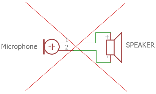
Well, NO, it is not possible. It is true that the microphone produces electrical energy but it is not sufficient to drive the huge load, that is speaker. The electrical output across the microphone provides a tiny amount of current which is too small to do something useful out of it and the amplitude is also low. On the other side, speaker needs huge current with large amplitude to produce enough movement and to generate the audible loud sound.
So, what is the solution? It is easy, we need to add a preamplifier, possibly Power amplifier or both to make something useful and to produce a louder sound from the output speaker.
In this project, we will make a small microphone amplifier using an LM386 power amplifier which is enough to produce loud audible sound out of a ½ Watt, 8 Ohms loudspeaker. If you are interested in amplifiers then check our other Audio Amplifier circuits. A simple amplifier circuit can also be constructed with transistor without using any amplifier IC.
Required Components
We need the following things to make the simple microphone amplifier-
- LM386
- 10uF / 16V capacitor
- 470uF / 16V
- 0.047uF / 16V Polystar Flim Capacitor
- 10R ¼ Watt
- 12V Power Supply unit
- 8 Ohms / .5 Watt Speaker
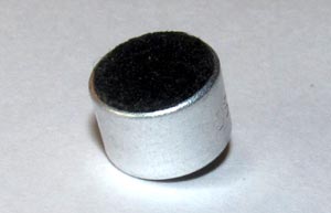
- Capsule or Electret Microphone
- .1uF capacitor
- 10k 1/4th Watt Resistor
- Bread Board
- Hook up wires
If you are interested in Vero board the following things will be additionally needed-
- Soldering Iron
- Soldering Wire
- Vero board.
Circuit Diagram
The schematic for simple Microphone to Speaker circuit is given below –

The circuit is exactly same as shown in the LM386 datasheet from Texas Instruments. We removed the 10k pot section and added additional bias circuitry of the microphone amplifier.

In the circuit diagram, the Amplifier is shown with the respective pin diagrams. The amplifier will provide 200x gain at output depending on the input. The 10uF capacitor across pin 1 and pin 8 is responsible for the 200x gain of the amplifier. We did not change the gain of the amplifier in our circuit construction. Also, the 250uF capacitor is connected across the Speaker. We have changed the value and used 470uF instead of 250uF capacitor. There is a 0.05uF capacitor along with a 10R resistor. This RC combination is called as snubber or clamp circuit which protect the amplifier from back EMF, produced by the speaker. We used a common but close value of 0.047uF instead of 0.05uF. Other circuitry and connections remain the same in our construction.
Also, the power amplifier can drive the wide range of load, from 4 Ohms to 32 Ohms and can be powered using 5V to 12V. We need to be careful about this rating otherwise we could damage the power amplifier or the output speaker.
LM386 Audio Amplifier IC
To connect the IC in breadboard or soldering in veroboard, we need to know the pin diagram of the Power Amplifier IC LML386. Pinout and Pin description of LM386 audio amplifier IC is given below.
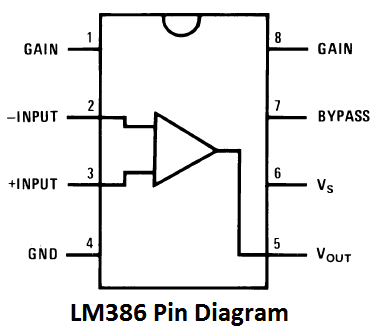
PIN 1 and 8: These are the gain control PINs, internally the gain is set to 20 but it can be increased up to 200 by using a capacitor between PIN 1 and 8. We have used 10uF capacitor C3 to get the highest gain i.e. 200. Gain can be adjusted to any value between 20 to 200 by using proper capacitor.
Pin 2 and 3: These are the input PINs for sound signals. Pin 2 is the negative input terminal, connected to the ground. Pin 3 is the positive input terminal, in which sound signal is fed to be amplified. In our circuit it is connected to the positive terminal of the condenser mic with a 100k potentiometer RV1. Potentiometer acts as volume control knob.
Pin 4 and 6: These are the power supply Pins of IC, Pin 6 for is +Vcc and Pin 4 is Ground. The circuit can be powered with voltage between 5-12v.
Pin 5: This is the output PIN, from which we get the amplified sound signal. It is connected to the speaker though a capacitor C2 to filter DC coupled noise.
Pin 7: This is the bypass terminal. It can be left open or can be grounded using a capacitor for stability
The IC consists of 8 pins, Pin - 1 and pin - 8 are the gain control pin. In the schematic 10uF capacitor is connected across pin 1 to pin 8. These two pin set the output gain of the amplifier. As per the datasheet a design, the 10uF capacitor is connected across these two pins and due to this, the output of the amplifier is fixed to 200x. Learn more about using LM386 audio amplifier IC here.

Electret Microphone
Now in input section, we have used an Electret microphone. Electret microphone uses electrostatic capacitor inside a capsule. It is widely used in a tape recorder, phones, mobiles, as well as microphone based headphone, Bluetooth headsets.
An Electrets microphone consists of two power pins, Positive and Ground. We are using Electret microphone from CUI INC. If we see the datasheet we can see the internal connection of the Electret microphone.

An Electret microphone consists of a Capacitor based material which changes the capacitance by the vibration. The capacitance changes the impedance of a Field Effect Transistor or FET. The FET needs to be biased by an external supply source using an external resistor. The RL is the external resistor which is responsible for the gain of the microphone. We used a 10k resistor as RL. We need an additional component, a ceramic capacitor, to block the DC and acquiring the AC audio signal. We used .1uF as our Microphone DC blocking capacitor. The total resistive load inside the electrets microphone is 2.2K.
To learn more about the microphone, see how MIC is used in electronics circuits.
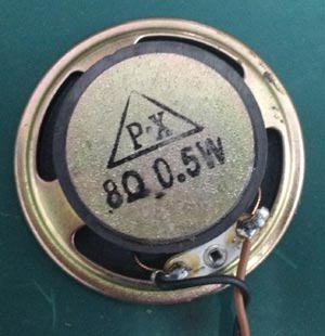
Speaker
And for the speaker, we used 8 Ohms, .5 Watt speaker. We can see the speaker in the below image-

We have constructed the Audio Voiceover circuit on a breadboard-
Working of the circuit is simple and can be understood from the pin description of the pins of LM386 IC Complete working of the circuit is explained in the video given below.
Points to Remember
For the uninterrupted working of the circuit please note the following points-
- Construct the circuit in a Veroboard. PCB is a good choice.
- Remove the R2 and use a potentiometer to adjust the gain of the microphone.
- Connect a long wire across Speaker and keep it at larger distance from the microphone. The feedback will be lower.
- Use additional filters to get clean sound output.
- Use proper low ripple power supply unit.
Comments
How do you discern which of…
How do you discern which of the two connections to the mic is the positive and which is ground? The one I have has no markings?
Thank you!
Also, is it easier to use a…
Also, is it easier to use a potentiometer in lieu of R2 to control the amplifier's gain, or is it more accurate maybe, than using the conventional method of placing the potentiometer in series with the 10uF cap between pins 1 and 8 of the LM386?
I was just curious as to why or how you chose the method you did for the gain control over others. Just asking out of personal curiosity and nothing more. I am about to try to construct this circuit myself. I enjoy learning all of this and any insights are greatly appreciated.
Many thanks, my friends.
Junk McNuggets
☠

Thanks for your article! I needed to test my Electret Mic, amp, and speaker - and was able to do so thanks to you!