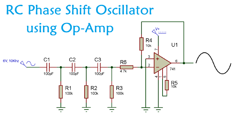
A Phase Shift Oscillator is an electronic oscillator circuit which produces sine wave output. It can either be designed by using transistor or by using an Op-amp as inverting amplifier. Generally, these phase shift oscillators are used as audio oscillators. In RC phase shift oscillator, 180 degree phase shift is generated by the RC network and another 180 degree is generated by the Op-amp, so the resulting wave is inverted by 360 degree.
Apart from generating the sine wave output they are also used to provide significant control over the phase shifting process. Other usages of phase shift oscillators are:
- In audio oscillators
- Sine Wave Inverter
- Voice Synthesis
- GPS units
- Musical Instruments.
Before we start designing the RC phase shift oscillator, Lets learn more about it phase and phase shift.
What is Phase and Phase Shift?
Phase is a full cycle period of a sinusoidal wave in a 360-degree reference. A complete cycle is defined as the interval required for the waveform to return its arbitrary initial value. Phase is denoted as a pointed position on this waveform cycle. If we see the sinusoidal wave we can easily identify the phase.
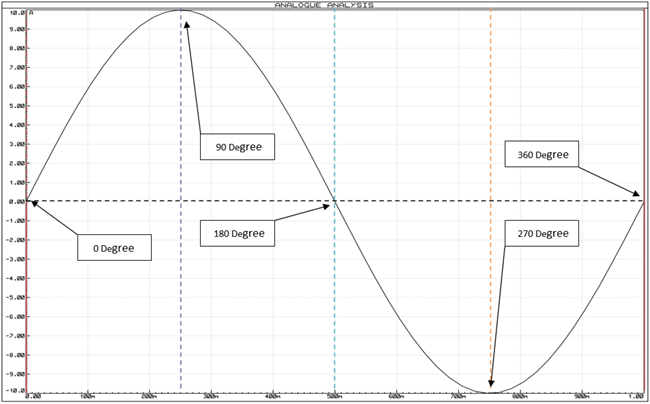
In the above image, a complete wave cycle is shown. The initial starting point of the sinusoidal wave is 0 degree in phase and if we identify each positive and negative peak and 0 points, we will get 90, 180, 270, 360-degree phase. So, when a sinusoidal signal starts it’s journey other than the 0-degree reference, we call it phase shift differentiating from 0-degree reference.
If we see the next image we will identify how a phase shifted sinusoidal wave look alike…
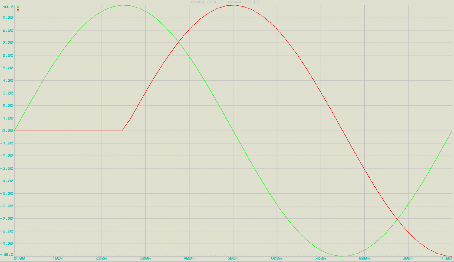
In this image, there are two AC sinusoidal signal wave presented, the first Green Sinusoidal wave is 360 degree in phase but the red one that is 90-degree phase shifted out of the green signal’s phase.
This phase shifting can be done using a simple RC network.
RC Phase Shift Oscillator
A simple RC phase shift oscillator provides a minimum phase shift of 60 degree.
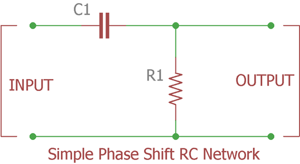
Above image is showing a single pole phase shift RC network or ladder circuit which shifts the phase of the input signal equal to or less than 60 degrees.
Ideally, the phase shift of the output wave of an RC circuit should be 90 degree, but in practical it is approx. 60 degree, as the capacitor is not ideal. The formula for calculating the phase angle of the RC network is mentioned below:
φ = tan-1(Xc / R)
Where, Xc is the reactance of the capacitor and R is the resistor connected in the RC network.
If we cascade there RC network, we will get 180-degree phase shift.

Now to create oscillation and sine wave output we need an active component, either Transistor or Op-amp in inverting configuration.
If you want to learn more about RC Phase Shift Oscillator, then follow the link
Why use Op-amp for RC Phase Shift Oscillator instead of Transistor?
There are some limitations in using Transistor for Building RC Phase Shift Oscillator:
- It is stable for low frequencies only.
- RC phase shift oscillator requires additional circuitry to stabilize the amplitude of the waveform.
- Frequency accuracy is not perfect and it is not immune to noisy interference.
- Adverse Loading effect. Due to cascade formation the second pole’s input impedance change the resistors resistance properties of the first pole filter. More the filters cascaded more the situation worsen up as it will affect the accuracy of calculated phase shift oscillator frequency.
Due to the attenuation across resistor and capacitor, the loss across each stage is increased and the total loss is approx 1/29th of the input signal.
As the circuit attenuates at 1/29th we need to recover the loss. Learn more about them in our previous tutorial.
RC Phase Shift Oscillator using Op-Amp
When we use op-amp for RC phase shift oscillator, it functions as an inverting amplifier. Initially, the input wave has been into the RC network, due to which we get 180 degree of phase shift. And, this output of RC is fed into the inverting terminal of the op-amp.
Now, as we know that the op-amp will produce a 180 degree of phase shift when functions as an inverting amplifier. So, we get a 360-degree of phase shift in the output sine wave. This RC phase shift oscillator using op-amp provides a constant frequency even under the varying load conditions.
Components Required
- Op-Amp IC – LM741
- Resistor – (100k – 3nos, 10k – 2nos, 4.7k)
- Capacitor – (100pF – 3nos)
- Oscilloscope
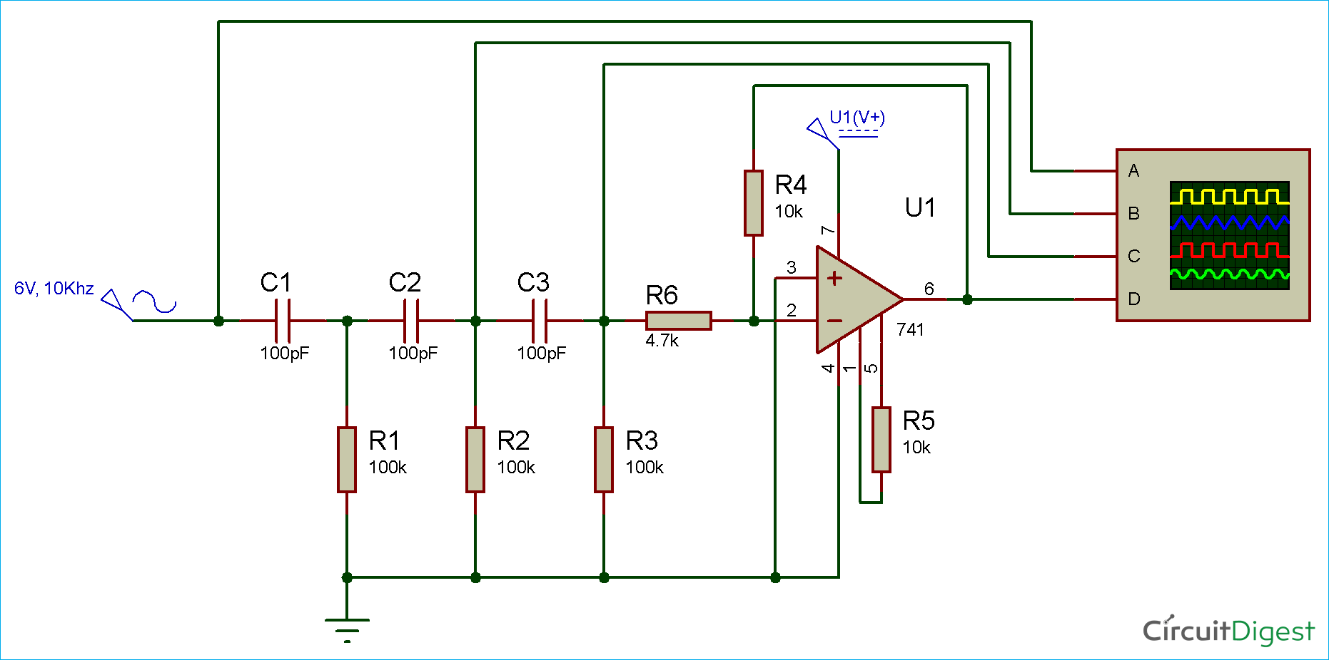
Circuit Diagram
Simulation of RC Phase Shift Oscillator using Op-Amp
RC phase shift oscillator provides an accurate sine wave output. As you can see in the simulation video in the end, we have set the probe of the oscilloscope to four stages of the circuit.
|
Oscilloscope Probe |
Wave Type |
|
First – A |
Input Wave |
|
Second – B |
Sine wave with 90 degree Phase Shift |
|
Third – C |
Sine wave with 180 degree Phase Shift |
|
Fourth – D |
Output Wave (Sine wave) with 360 degree Phase Shift |
Here, the feedback network is offering a phase shift of 180 degree. We are getting 60 degree from each of the RC network. And, the remaining 180 degree phase shift is generated by the op-amp in the inverting configuration.
For calculating the frequency of oscillation use the below formula:
F = 1 / 2πRC√2N
The disadvantage of RC phase shift oscillator using op-amp is that it can’t be used for high frequency applications. Because whenever the frequency is too high the capacitor’s reactance is very low and it act as a short circuit.



what is the purpose of R5 in this circuit?
Thank you,