

In some applications, user input is required to control the functions of a device. There are different kinds of user input methods used in the embedded and digital electronics. The touch sensor is one of them. Touch sensor is an important and widely used input device to interface with a microcontroller and it has made inputting data simpler. There are individual places where the touch sensor can be used, whether it can be a mobile phone or an LCD monitor switch. However, there are many types of sensors available in the market but Capacitive touch sensor is the widely used type in touch sensor segment.
In the previous tutorial, we have done Controlling Light using Touch Sensor and 8051 Microcontroller, Now in this project, the same touch sensor will be interfaced with Arduino UNO. The Arduino is a widely popular and easily available development board.
We previously used touch based input methods using capacitive touch pads with different microcontrollers such as:
Touch Sensor
The touch sensor, which will be used for this project is a capacitive touch sensor module and the sensor driver is based on the driver IC TTP223. The operating voltage of the TTP223 IC is from the 2 V to 5.5 V and the current consumption of the touch sensor is very low. Due to the inexpensive, low current consumption, and easy to integrate support, the touch sensor with TTP223 becomes popular in the capacitive touch sensor segment.

In the above image, both sides of the sensor are shown where the pinout diagram is clearly visible. It also has a solder jumper which can be used to reconfigure the sensor in respect of the output. The jumper is A and B. Default configuration or in the default state of the solder jumper, the output changes from LOW to HIGH when the sensor is touched. However, when the jumper is set and the sensor is reconfigured, the output changes its state when the touch sensor detects the touch. The sensitivity of the touch sensor can be also configured by changing the capacitor. For the detailed info,go through the datasheet of the TTP 223 which will be very useful.
Below chart is showing different outputs at different jumper settings-
| Jumper A | Jumper B | Output Lock State | Output TTL level |
| Open | Open | No-lock | High |
| Open | Close | Self-lock | High |
| Close | Open | No-Lock | Low |
| Close | Close | Self-Lock | Low |
For this project, the sensor will be used as the default configuration which is available on the factory release condition.
Appliances can be controlled by using the touch sensor, and by interfacing it with a microcontroller. In this project, the touch sensor will be used to control a Light Bulb as ON or OFF using Arduino UNO and Relay.
Get to know about Relay
To interface the relay, it is important to have a fair idea about the relay’s pin description. The pinout of the relay can be seen in the below image-

NO is normally open and NC is normally connected. L1 and L2 are the two terminals of the Relay coil. When the Voltage is not applied, the relay is turned off and the POLE gets connected with the NC pin. When the voltage is applied across the coil terminals, L1 and L2 of the relay gets turned ON and the POLE gets connected with the NO. So, the connection between POLE and NO can be switched ON or OFF by changing the operations state of the Relay. It is highly advisable to check the relay specification before the application. The relay has an operating voltage across the L1 and L2. Some relay works with 12V, some with the 6V and some with the 5V. Not only has this, the NO, NC and POLE also had a voltage and current rating. For our application, we are using 5V Relay with a 250V, 6A rating on the switching side.
Components Required
- Arduino UNO
- The USB cable for programming and power
- Standard Cubic Relay - 5V
- 2k resistor -1 pc
- 4.7k resistor - 1 pc
- BC549B transistor
- TTP223 Sensor module
- 1N4007 Diode
- Light Bulb With Bulb Holder
- A breadboard
- A phone charger to connect the Arduino via USB cable.
- Lots of hookup wires or berg wires.
- Arduino programming platform.
2k resistor, BC549B, 1N4007, and the Relay can be replaced with a Relay Module.
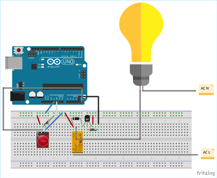
Circuit Diagram
The schematic for connecting touch sensor with Arduino is simple and can be seen below,

The transistor is used to switch on or off the Relay. This is due to the Arduino GPIO pins are not capable to provide enough current to drive the Relay. The 1N4007 is required for EMI blocking during Relay on or off situation. The diode is acting as a freewheel diode. The touch sensor is connected with the Arduino UNO board.
The circuit is constructed on a breadboard with the Arduino as below.
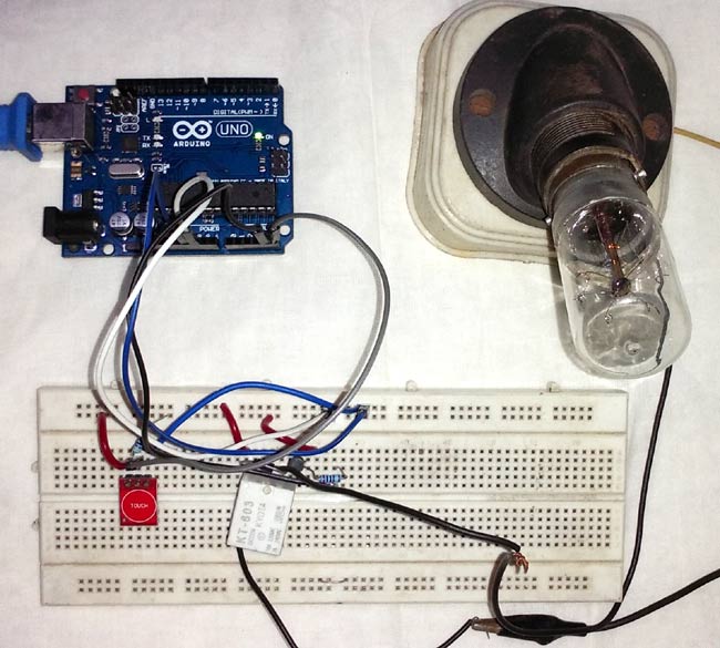
The proper breadboard connection can be seen in the below schematic.
Programming Arduino UNO to Control Light Bulb using Touch Sensor
Complete program with working Video is given at the end. Here we are explaining few important parts of the code. The Arduino UNO will be programmed using Arduino IDE. Firstly, the Arduino library is included to access all default functions of Arduino.
#include <Arduino.h>
Define all the pin numbers where relay and touch sensor will be connected. Here, the touch sensor is connected to pin A5. The inbuilt LED is also used which is directly connected in the board to pin 13. The relay is connected to pin A4.
/*
 * Pin Description
 */
int Touch_Sensor = A5;
int LED = 13;
int Relay = A4;
Define the pin mode i.e. what should be the pin function whether as input or output. Here touch sensor is made input. Relay and LED pins are output.
/*
 * Pin mode setup
 */
void setup() {
            pinMode(Touch_Sensor, INPUT);
            pinMode(LED, OUTPUT);
            pinMode(Relay, OUTPUT);
}
Two integers are declared where the ‘condition’ is used to hold the sensor’s condition whether it is touched or not. The ‘state’ is used for holding the state of the LED and Relay, on or off.
/*
 * Programme flow Description
 */
int condition = 0;
int state = 0; //To hold the switch state.
The touch sensor changes the logic 0 to 1 when it is touched. This is read by the digitalRead() function and the value is stored in the condition variable. When the condition is 1, the state of the LED and Relay gets changed. However, to detect the touch accurately, a debounce delay is used. The debounce delay, delay(250); is used to confirm the single touch.
void loop() {
            condition = digitalRead(A5); // Reading digital data from the A5 Pin of the Arduino.
            if(condition == 1){
                        delay(250); // de-bounce delay.
                        if(condition == 1){
                                    state = ~state; // Changing the state of the switch.
                                    digitalWrite(LED, state);
                                    digitalWrite(Relay, state);
                        }
            }
}

Testing the Working of Touch Sensor TTP223
The circuit is tested in the breadboard with a low power bulb connected to it.
Note that this project uses 230-240V AC voltage, so it is advised to be careful while using bulb. If you have any doubt or suggestion, then please comment below.
Complete Project Code
/*//==============================================================================//
 * TTP223 interfacing with Arduino
 * Date: - 3-04-2019
 * Author:- Sourav Gupta
 * For:- circuitdigest.com
 *///=============================================================================//
#include <Arduino.h>
//#define ON 1
//#define OFF 0
/*
 * Pin Description
 */
int Touch_Sensor = A5;
int LED = 13;
int Relay = A4;
/*
 * Programme flow Description
 */
int condition = 0;
int state = 0; //To hold the switch state.
/*
 * Pin mode setup
 */
void setup() {
pinMode(Touch_Sensor, INPUT);
pinMode(LED, OUTPUT);
pinMode(Relay, OUTPUT);
}
void loop() {
condition = digitalRead(A5); // Reading digital data from the A5 Pin of the Arduino.
if(condition == 1){
delay(250); // de-bounce delay.
if(condition == 1){
state = ~state; // Changing the state of the switch.
digitalWrite(LED, state);
digitalWrite(Relay, state);
}
}
}

Dear Sourav,
may I ask what the purpose of the arduino is in this simple application? If one wanted to turn a light on and off with the TTP223 it can be done directly, either using the TTP223 to drive a relay through a buffer transistor, or driving a "Triac Interface circuit," or Solid State Relay (SSR)... The TTP223 can be configured in either latching-toggle mode or momentary.
I am currently designing a Triac Interface circuit and was wondering what the performance of the TTP223 is when it's connected to the "live" 240V line and hence following the supply up and down by +/-330V with resepct to ground. The TTP223 uses it's own internal 500Khz oscillator to detect a "touch" and a sheet of plastic or glass between the TTP223 input and the touch pad would provide perfectly adequate isolation, and so pose no safety risk.... Have you looked at this approach?
kind regards, Frank (I am retured IC design engineer)