
Home Automation has always been inspiring projects for most of us. Toggling an AC load from the comfort of our chairs or bed of any room without reaching for the switch in another room sounds cool doesn’t it!!. And now in the era of IoT, thanks to the ESP8266 module which made it easy to control anything from anywhere in the world.
In this IoT based project, we will use Adafuit IO to control Home appliaces from a webpage using ESP8266 and PIC microcontroller. We have connected three AC light as loads and they can be controlled remotely using either your phone or computer. Here ESP8266 is used with PIC microcontroller so learn about Interfacing ESP8266 with PIC16F877A Microcontroller before proceeding. Also check IoT projects section to learn more ESP8266 Wi-Fi module.
Component Required
- ESP8266
- PIC microcontroller(PIC16f877A)
- 12V 5A Electromagnetic Relay Module -1
- 12v Power supply (12V/1A or above) -1
- LM7805 Voltage Regulator -1
- LM317 Regulator -1
- 10k ohm Resistor -1
- 1k Resistor – 3
- 10k Pot – 1
- 1k Pot -1
- 16x2 LCD
- 1000uF capacitor -1
- 10uF capacitor -2
- Wires for connection
- 18.432 MHz Crystal oscillator -1
- LED -2
- 22pF capacitor -2
- BreadBoard or PCB (optional)
Circuit Diagram

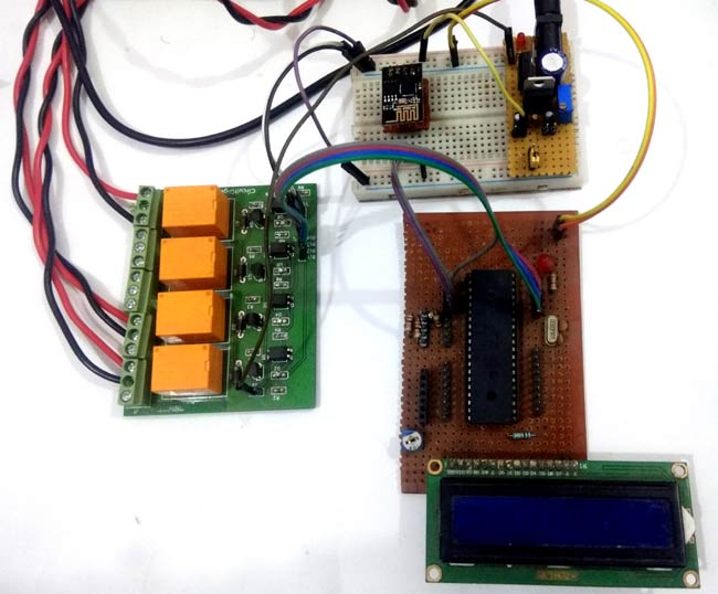
In Web controlled Home Automation project, we have used PIC microcontroller PIC16F877A for performing all the operations. It will communicate with ESP8266 Wi-Fi module to send and receive data from the Adafruit server and take action accordingly to turn ON/OFF relay or load and displaying the status of loads over LCD. We have used 16x2 LCD display for displaying the status of connected AC appliances.
In this project we have three power supplies:
- As we have used a 12v relay module we need 12v so we have used a 12v adaptor to power the relay.
- We needed 5v for powering the PIC microcontroller, LCD and some of the relay module circuit. So we have used a 7805 voltage regulator connected with a 12v supply. This voltage regulator provides 5v output.
- A 3.3v power supply is used for powering the ESP8266 as it works on 3.3v. This supply is made by using LM317 voltage regulator which can be configurable to 3.3v by using some voltage divider circuitry with this. Learn more about creating a LM317 based variable power supply.
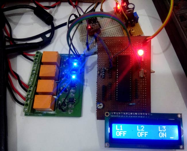
All the connections for this project have been shown in the circuit diagram. The final setup will look like this:

Setup Adafruit IO for IoT Home Automation
In this project, we are going to control some home AC appliance via a web page crated using Adafruit IO. Adafruit IO is a simple to use internet service that easily enables IoT devices to GET and POST data. Additionally, it can be used to create GUI interfaces for viewing data, controlling devices, and triggers for alerts/warnings.
Follw below steps to setup Adafruit IO for IoT Home Automation
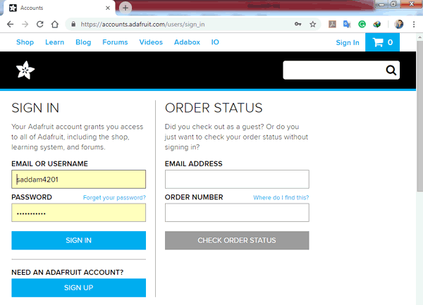
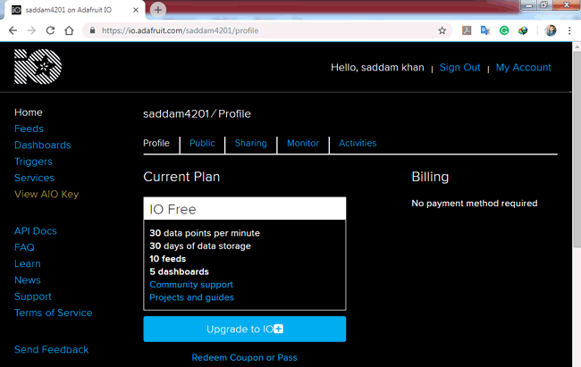
Step 1: in this step, we have to create an account on adafruit.io or if you already have an account just login into it.
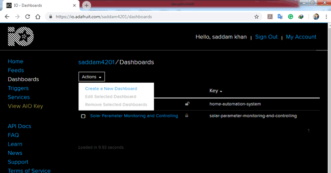
Step 2: Create a dashboard by clicking on ‘Dashboards’ at the left side of the page and then click on ‘Action’ and then on ‘Create a New Dashboard’.
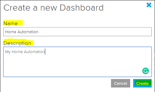
Now a pop-up window form will open, fill in any name like Home Automation and click on Create. You can also add some description related to project.
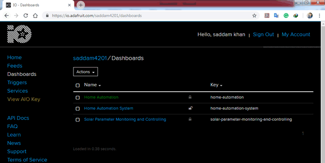
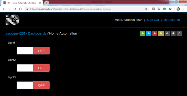
Step 3: Now click on the newly created dashboard
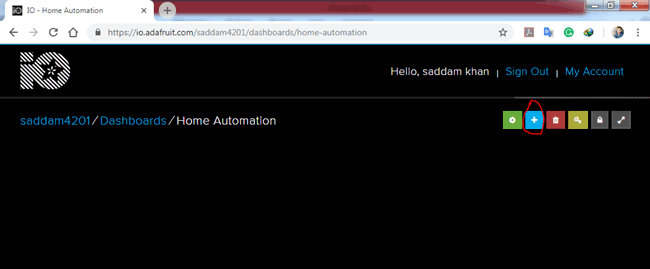
Now we need to click on + size at the right side of the page under blue squire and red circle.
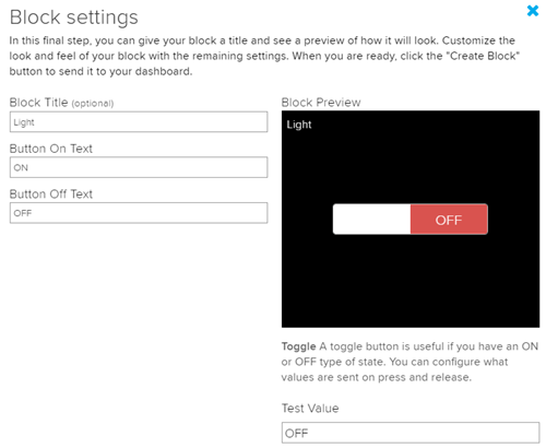
Now another pop-up window open to select desired new block item like ON/OFF switch.
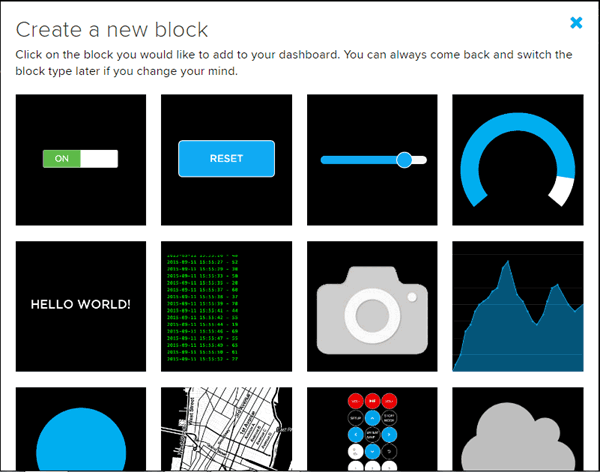
After selecting the Block (On/Off button) a new pop-up window will open. Enter here the name of your new feed like Light1 or and click on create.
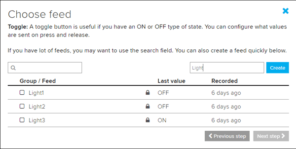
Now click on a newly created feed and fill some details and click over create a block.
You can create more feeds and blocks according to requirement. Here we have created three for controlling three lights from this web interface
Step 4: Now click on ‘KEY’ symbol on the same page and copy username and the active key given there.
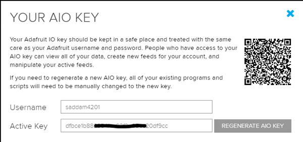
Step 5: Now open the code and replace the username with your username everywhere in the code, also replace the MQTTPassword with the active key in the code. Complete code is given at the end of this project.
const char MQTTHost[] = "io.adafruit.com";
const char MQTTPort[] = "1883";
const char MQTTClientID[] = "ABCDEF";
const char MQTTTopicRelay1[] = "saddam4201/feeds/Light1";
const char MQTTTopicRelay2[] = "saddam4201/feeds/Light2";
const char MQTTTopicRelay3[] = "saddam4201/feeds/Light3";
const char MQTTTopicRelay4[] = "saddam4201/feeds/Light4";
const char MQTTProtocolName[] = "MQTT";
const char MQTTLVL = 0x03;
const char MQTTFlags = 0xC2;
const unsigned int MQTTKeepAlive = 60;
const char MQTTUsername[] = "saddam4201";                // put your Username
const char MQTTPassword[] = "xxxxxxxxxxxxxxxxxxxxxxxxxxxxxxxx";    // Put Your Password
const char MQTTQOS = 0x00;
const char MQTTPacketID = 0x0001;
Step 6: Now compile and upload the code into PIC microcontroller, if you are new with PIC microcontroller then follow our Getting started guide for PIC MCU. Also check the Video at the end to understand the working of the project.
MQTT Protocol
This IoT based Home Automation Project uses MQTT protocol for exchanging data between server and client. This protocol is very fast compared to the TCP/IP protocol. And the working concept is also different from the TCP/IP protocol. This protocol has three main components.
- Publish
- Broker
- Subscriber
According to MQTT.org (official website), “MQTT stands for MQ Telemetry Transport. It is a publish/subscribe, extremely simple and lightweight messaging protocol, designed for constrained devices and low-bandwidth, high-latency or unreliable networks. The design principles are to minimize network bandwidth and device resource requirements whilst also attempting to ensure reliability and some degree of assurance of delivery. These principles also turn out to make the protocol ideal of the emerging “machine-to-machine” (M2M) or “Internet of Things” world of connected devices, and for mobile applications where bandwidth and battery power are at a premium.”
We previously used MQTT Client with Amazon AWS for IoT Projects.

Programming Explanation
Programming part of this Adafruit.io Home Automation is a little bit difficult because of MQTT protocol and its frame format. But if you don’t want to go into this then you can directly try the code given at the end. Here we have explained few parts of code below:
First of all, include all the required libraries and set configuration bits for PIC Microcontroller.
#define _XTAL_FREQ 18432000
#include <xc.h>
#include<pic.h>
#include <stdio.h>
#include <stdlib.h>
#include <string.h>

// BEGIN CONFIG
#pragma config FOSC = HS // Oscillator Selection bits (HS oscillator)
#pragma config WDTE = OFF // Watchdog Timer Enable bit (WDT enabled)
#pragma config PWRTE = OFF // Power-up Timer Enable bit (PWRT disabled)
#pragma config BOREN = ON // Brown-out Reset Enable bit (BOR enabled)
#pragma config LVP = OFF // Low-Voltage (Single-Supply) In-Circuit Serial Programming Enable bit (RB3 is digital I/O, HV on MCLR must be used for programming)
#pragma config CPD = OFF // Data EEPROM Memory Code Protection bit (Data EEPROM code protection off)
#pragma config WRT = OFF // Flash Program Memory Write Enable bits (Write protection off; all program memory may be written to by EECON control)
#pragma config CP = OFF // Flash Program Memory Code Protection bit (Code protection off)
//END CONFIG
After this, we have defined some macros that are used to declare pins for LCD and other GPIOs.
#define uchar unsigned char
#define uint unsigned int

#define LCDPORTDIR TRISA
#define LCDPORT PORTA
#define RS RE1
#define EN RE0

#define relay1dir TRISC0
#define relay2dir TRISC1
#define relay3dir TRISC2
#define relay4dir TRISC4
#define relay1 RC0
#define relay2 RC1
#define relay3 RC2
#define relay4 RC4

#define leddir TRISC3
#define led RC3

#define txDir TRISD0
#define tx RD0
Now in giving part of the code, we have some variables that we have sued in this project
volatile char buf[95];
uchar buf1[70];
uchar buf2[15];
int retry;
int restartFlag=0;
volatile char index=0;
volatile char flag=0;
volatile int msCount=0;
volatile char g_timerflag=1;
volatile int counter=0;
volatile char sec=0;
unsigned int topiclength;
unsigned char topic[25];
unsigned char encodedByte;
int X;
Below function is used for Wi-Fi initialization which is responsible for initializing wifi module and connect ESP8266 with Wi-Fi hotspot or Wi-Fi router.
void espInitize()
{
    lcdwrite(0x01, CMD);
    lcdprint("ESP Initilizing");
    serialprintln("AT+RST");
    __delay_ms(5000);
    espInit("AT","OK",2);
    espInit("ATE1","OK",2);
    espInit("AT+CWMODE=3","OK",2);
    espInit("AT+CWQAP","OK",2);
    espInit("AT+CWJAP=\"wifi_name\",\"password\"","OK",3);
    serialprintln("AT+CIFSR");
                serialFlush();
    __delay_ms(500);
}
Below code is used to configure MQTT and adafrut.io.
const char MQTTHost[] = "io.adafruit.com";
const char MQTTPort[] = "1883";
const char MQTTClientID[] = "ABCDEF";
const char MQTTTopicRelay1[] = "saddam4201/feeds/Light1";
const char MQTTTopicRelay2[] = "saddam4201/feeds/Light2";
const char MQTTTopicRelay3[] = "saddam4201/feeds/Light3";
const char MQTTTopicRelay4[] = "saddam4201/feeds/Light4";
const char MQTTProtocolName[] = "MQTT";
const char MQTTLVL = 0x03;
const char MQTTFlags = 0xC2;
const unsigned int MQTTKeepAlive = 60;
const char MQTTUsername[] = "saddam4201";                // put your Username
const char MQTTPassword[] = "xxxxxxxxxxxxxxxxxxxxxxxxxxxxxxxx";    // Put Your Password
const char MQTTQOS = 0x00;
const char MQTTPacketID = 0x0001;
Given function is used to connect with Adafruit IO broker and subscribing the topics that we have used in this project.
void restartESP()
{
            espInitize();
            espInit("AT+CIPSTART=\"TCP\",\"io.adafruit.com\",1883","CONNECT",5)
            SendConnectPacket()
                                                SendSubscribePacket(&MQTTTopicRelay1[0],strlen(MQTTTopicRelay1))
                                                SendSubscribePacket(&MQTTTopicRelay2[0],strlen(MQTTTopicRelay2))
                                                SendSubscribePacket(&MQTTTopicRelay3[0],strlen(MQTTTopicRelay3))
            lcdwrite(1,CMD);
            led=1;
}
Given function is for connecting with Adafruit IO MQTT broker
int SendConnectPacket(void)
{
  int txIndex=0;
  unsigned int MQTTProtocolNameLength = strlen(MQTTProtocolName);
  unsigned int MQTTClientIDLength = strlen(MQTTClientID);
  unsigned int MQTTUsernameLength = strlen(MQTTUsername);
  unsigned int MQTTPasswordLength = strlen(MQTTPassword);
  X = MQTTProtocolNameLength + 2 + 4 + MQTTClientIDLength + 2 + MQTTUsernameLength + 2 + MQTTPasswordLength + 2;
  do
  {
    encodedByte = X % 128;
    X = X / 128;
    if ( X > 0 )
    {
      encodedByte |= 128;
    }
  } while ( X > 0 );

  buf1[txIndex++]=0x10;
  buf1[txIndex++]=encodedByte;
  buf1[txIndex++]=MQTTProtocolNameLength<<8;
  buf1[txIndex++]=MQTTProtocolNameLength;
  memcpy((unsigned char *)&buf1[txIndex],(unsigned char *)&MQTTProtocolName,MQTTProtocolNameLength);
Given function is used to send subscribe packet to MQTT broker
int SendSubscribePacket(char topic[], int topiclength)
{
  X = 2 + 2 + topiclength + 1;
  do
  {
    encodedByte = X % 128;
    X = X / 128;
    if ( X > 0 )
    {
      encodedByte |= 128;
    }
    //serialwrite(encodedByte);
  } while ( X > 0 );

  int txIndex=0;
  buf1[txIndex++]=0x82;
  buf1[txIndex++]=encodedByte;
  buf1[txIndex++]=MQTTPacketID<<8;
  buf1[txIndex++]=MQTTPacketID;
  buf1[txIndex++]=topiclength<<8;
  buf1[txIndex++]=topiclength;
  memcpy(&buf1[txIndex],(char *)&topic[0],topiclength);
  txIndex+=topiclength;
We also have some LCD and Serial communication-related functions by can be easily understood by looking at the complete code given below. Also check the working Video of this PIC based Home Automation project at the end of the Article.
So with the use of Adafruit.io, it becomes very easy to control the microcontroller pins from anywhere in the world using the the internet.
Complete Project Code
#define _XTAL_FREQ 18432000
#include <xc.h>
#include<pic.h>
#include <stdio.h>
#include <stdlib.h>
#include <string.h>

// BEGIN CONFIG
#pragma config FOSC = HS // Oscillator Selection bits (HS oscillator)
#pragma config WDTE = OFF // Watchdog Timer Enable bit (WDT enabled)
#pragma config PWRTE = OFF // Power-up Timer Enable bit (PWRT disabled)
#pragma config BOREN = ON // Brown-out Reset Enable bit (BOR enabled)
#pragma config LVP = OFF // Low-Voltage (Single-Supply) In-Circuit Serial Programming Enable bit (RB3 is digital I/O, HV on MCLR must be used for programming)
#pragma config CPD = OFF // Data EEPROM Memory Code Protection bit (Data EEPROM code protection off)
#pragma config WRT = OFF // Flash Program Memory Write Enable bits (Write protection off; all program memory may be written to by EECON control)
#pragma config CP = OFF // Flash Program Memory Code Protection bit (Code protection off)
//END CONFIG

#define uchar unsigned char
#define uint unsigned int

#define LCDPORTDIR TRISA
#define LCDPORT PORTA
#define RS RE1
#define EN RE0

#define relay1dir TRISC0
#define relay2dir TRISC1
#define relay3dir TRISC2
#define relay4dir TRISC4
#define relay1 RC0
#define relay2 RC1
#define relay3 RC2
#define relay4 RC4

#define leddir TRISC3
#define led RC3

#define txDir TRISD0
#define tx RD0

#define HIGH 1
#define LOW 0

#define maxRetry 3

#define buflen 95

volatile char buf[95];
uchar buf1[70];
uchar buf2[15];
int retry;
int restartFlag=0;
volatile char index=0;
volatile char flag=0;
volatile int msCount=0;
volatile char g_timerflag=1;
volatile int counter=0;
volatile char sec=0;
unsigned int topiclength;
unsigned char topic[25];
unsigned char encodedByte;
int X;

const char MQTTHost[] = "io.adafruit.com";
const char MQTTPort[] = "1883";
const char MQTTClientID[] = "ABCDEF";
const char MQTTTopicRelay1[] = "saddam4201/feeds/Light1";
const char MQTTTopicRelay2[] = "saddam4201/feeds/Light2";
const char MQTTTopicRelay3[] = "saddam4201/feeds/Light3";
const char MQTTTopicRelay4[] = "saddam4201/feeds/Light4";
const char MQTTProtocolName[] = "MQTT";
const char MQTTLVL = 0x03;
const char MQTTFlags = 0xC2;
const unsigned int MQTTKeepAlive = 60;
const char MQTTUsername[] = "saddam4201";                // put your Username
const char MQTTPassword[] = "xxxxxxxxxxxxxxxxxxxxxxxxxxxxxxxx";    // Put Your Password
const char MQTTQOS = 0x00;
const char MQTTPacketID = 0x0001;

#define netCheckSec 60
int initFlag=1;

enum
{
 CMD,
 DATA,
 SBIT_CREN=4,
 SBIT_TXEN,
 SBIT_SPEN,
};

int SendConnectPacket(void);
int SendSubscribePacket(char topic[], int);

void lcdwrite(uchar ch,uchar rw)
{
     LCDPORT= ch>>4 & 0x0F;
     RS=rw;
     EN=1;
     __delay_ms(5);
     EN=0;
     LCDPORT= ch & 0x0F;
     EN=1;
     __delay_ms(5);
     EN=0;
}

lcdprint(char *str)
{
    while(*str)
    {
        lcdwrite(*str++,DATA);
        //__delay_ms(20);
    }
}

lcdbegin()
{
    uchar lcdcmd[5]={0x02,0x28,0x0E,0x06,0x01};
    uint i=0;
    for(i=0;i<5;i++)
    lcdwrite(lcdcmd[i], CMD);
}

void serialbegin(unsigned long baudrate)
{
    TXSTAbits.BRGH = 1;                                     //Setting High Baud Rate
    SPBRG=(_XTAL_FREQ/(long)(16UL*baudrate))-1;
    TXSTAbits.SYNC = 0;                                     //Setting Asynchronous Mode, ie UART
    RCSTAbits.SPEN = 1;                                     //Enables Serial Port
    TRISC7 = 1;                                   //As Prescribed in Datasheet
    TRISC6 = 0;                                   //As Prescribed in Datasheet
    RCSTAbits.CREN = 1;                                     //Enables Continuous Reception
    TXSTAbits.TXEN = 1;                                     //Enables Transmission

    //RCONbits.IPEN   = 1; // ENABLE interrupt priority
    GIE  = 1; // ENABLE interrupts
    INTCONbits.PEIE = 1; // ENable peripheral interrupts.
    PIE1bits.RCIE   = 1; // ENABLE USART receive interrupt
    PIE1bits.TXIE   = 0; // disable USART TX interrupt

// make sure the RX flag is clear
    PIR1bits.RCIF = 0;

}

void serialwrite(char ch)
{
    while(TXIF==0);  // Wait till the transmitter register becomes empt
    TXREG=ch;        // load the char to be transmitted into transmit reg
        TXIF=0;          // Clear transmitter flag
    __delay_ms(1);
}

serialprint(char *str)
{
    while(*str)
    {
        serialwrite(*str++);
    }
}

serialprintln(char *str)
{
    while(*str)
    {
        serialwrite(*str++);
    }
    serialwrite(0x0D);
    serialwrite(0x0A);
}

char UART_RxChar()
{
    while(RCIF==0);    // Wait till the data is received
    RCIF=0;
    uchar ch=RCREG;// Clear receiver flag
    lcdwrite(ch, DATA);
    return(ch);     // Return the received data to calling function
}

void serialFlush()
{
    for(int i=0;i<buflen;i++)
    {
        buf[i]=0;
    }
    index=0;
}

void write(char ch)
{
/* tx=0;
__delay_us(8);
for(int i=0;i<8;i++)
{
if(ch & 1)
tx=1;
else
tx=0;
__delay_us(8);
ch>>=1;
}
tx=1;
__delay_us(8); */
}


void Serialprintdebug(char *str)
{
    while(*str)
    {
write(*str);
            str++;
}
}

void timer()           // 10 -> 1us
{
    OPTION_REG = (1<<2);  // Timer0 with external freq and 32 as prescalar
    TMR0=100;       // Load the time value for 1ms delay
    TMR0IE=1;       //Enable timer interrupt bit in PIE1 register
    GIE=1;          //Enable Global Interrupt
    PEIE=1;         //Enable the Peripheral Interrupt
}

void timerOn(uint time)
{
    msCount=time;
    TMR0=99;
    PEIE=1;
}

void timerOff()
{
    PEIE=0;
}

void delay(unsigned int t)
{
    for(int i=0;i<t;i++)
        for(int j=0;j<1000;j++);
}

int espInit(char *cmd, char *res, int time)
{
    retry=0;
    while(1)
    {
        if(flag == 0)
        serialFlush();
        serialprintln(cmd);
        long csec=sec;
        while(sec < csec+time)
        {
            if(strstr(buf,res))
            {
                return 0;
            }
            __delay_ms(1000);
        }
          retry++;
          if(retry>maxRetry)
          {
             return 1;
          }
    }
    return 1;
}

void espInitize()
{
    lcdwrite(0x01, CMD);
    lcdprint("ESP Initilizing");
    serialprintln("AT+RST");
    __delay_ms(5000);
    espInit("AT","OK",2);
    espInit("ATE1","OK",2);
    espInit("AT+CWMODE=3","OK",2);
    espInit("AT+CWQAP","OK",2);
    espInit("AT+CWJAP=\"wifi_name\",\"password\"","OK",3);
    serialprintln("AT+CIFSR");
serialFlush();
    __delay_ms(500);
}

void checkBuffer()
{
     if(strstr(buf,"Light1ON"))
            relay1=0;
     else if(strstr(buf,"Light1OFF"))
            relay1=1;
     else if(strstr(buf,"Light2ON"))
            relay2=0;
     else if(strstr(buf,"Light2OFF"))
            relay2=1;
     else if(strstr(buf,"Light3ON"))
            relay3=0;
     else if(strstr(buf,"Light3OFF"))
            relay3=1;
     else if(strstr(buf,"Light4ON"))
            relay4=0;
     else if(strstr(buf,"Light4OFF"))
              relay4=1;
     serialFlush();
}

void restartESP()
{
            espInitize();
            espInit("AT+CIPSTART=\"TCP\",\"io.adafruit.com\",1883","CONNECT",5)
            SendConnectPacket()
SendSubscribePacket(&MQTTTopicRelay1[0],strlen(MQTTTopicRelay1))
SendSubscribePacket(&MQTTTopicRelay2[0],strlen(MQTTTopicRelay2))
SendSubscribePacket(&MQTTTopicRelay3[0],strlen(MQTTTopicRelay3))
            lcdwrite(1,CMD);
            led=1;
}

int main()
{
  ADCON1=0b00000110;
  relay4dir= 0;
  relay1dir= 0;
  relay2dir= 0;
  relay3dir= 0;
  leddir=0;
  LCDPORTDIR=0x00;
  TRISE=0;
  txDir=0;
  lcdbegin();
  lcdprint("Home Automation ");
  lcdwrite(192,CMD);
  lcdprint("Using PIC16F877A");
  __delay_ms(2000);
  //Serialprintdebug("Saddam Khan");
  index=0;
  serialbegin(115200);
  timer();
  timerOn(1000);
  lcdwrite(1,CMD);
  lcdprint("Please Wait...");
  led=0;
  restartESP();
  while(1)
  {
      if(flag==1)
      {
          checkBuffer();
          flag=0;
      }

  lcdwrite(0x80,CMD);
  lcdprint("L1    L2    L3");
  lcdwrite(192,CMD);
  if(relay1)
  lcdprint("OFF");
  else
  lcdprint("ON ");

    lcdwrite(198,CMD);
  if(relay2)
  lcdprint("OFF");
  else
  lcdprint("ON ");


  lcdwrite(204,CMD);
  if(relay3)
  lcdprint("OFF");
  else
  lcdprint("ON ");

  __delay_ms(1000);
  }
  return 0;
}

void interrupt SerialRxPinInterrupt(void)
{
    if((PIR1bits.RCIF == 1) && (PIE1bits.RCIE == 1))
    {

        uchar ch=RCREG;
        if(ch != NULL)
        {
            buf[index]=ch;
            if(index>=30)
                flag=1;
           index++;
            if(index>=buflen)
             index=0;
        }
        RCIF = 0; // clear rx flag
    }

   if(INTCONbits.TMR0IE && INTCONbits.TMR0IF)
   {
    TMR0IF=0;
    TMR0=112;
    counter++;
    if(counter >= msCount)
    {
        sec++;
        if(sec >= netCheckSec)
        {
           g_timerflag=1;
           sec=0;
        }
        counter=0;
    }
    }
}

int SendConnectPacket(void)
{
  int txIndex=0;
  unsigned int MQTTProtocolNameLength = strlen(MQTTProtocolName);
  unsigned int MQTTClientIDLength = strlen(MQTTClientID);
  unsigned int MQTTUsernameLength = strlen(MQTTUsername);
  unsigned int MQTTPasswordLength = strlen(MQTTPassword);
  X = MQTTProtocolNameLength + 2 + 4 + MQTTClientIDLength + 2 + MQTTUsernameLength + 2 + MQTTPasswordLength + 2;
  do
  {
    encodedByte = X % 128;
    X = X / 128;
    if ( X > 0 )
    {
      encodedByte |= 128;
    }
  } while ( X > 0 );

  buf1[txIndex++]=0x10;
  buf1[txIndex++]=encodedByte;
  buf1[txIndex++]=MQTTProtocolNameLength<<8;
  buf1[txIndex++]=MQTTProtocolNameLength;
  memcpy((unsigned char *)&buf1[txIndex],(unsigned char *)&MQTTProtocolName,MQTTProtocolNameLength);
  txIndex+=MQTTProtocolNameLength;
  buf1[txIndex++]=MQTTLVL;
  buf1[txIndex++]=MQTTFlags;
  buf1[txIndex++]=MQTTKeepAlive<<8;
  buf1[txIndex++]=MQTTKeepAlive;
  buf1[txIndex++]=MQTTClientIDLength<<8;
  buf1[txIndex++]=MQTTClientIDLength;
  memcpy(&buf1[txIndex],(char *)&MQTTClientID,MQTTClientIDLength);
  txIndex+=MQTTClientIDLength;
  buf1[txIndex++]=MQTTUsernameLength<<8;
  buf1[txIndex++]=MQTTUsernameLength;
  memcpy(&buf1[txIndex],(char *)&MQTTUsername,MQTTUsernameLength);
  txIndex+=MQTTUsernameLength;
  buf1[txIndex++]=MQTTPasswordLength<<8;
  buf1[txIndex++]=MQTTPasswordLength;
  memcpy(&buf1[txIndex],(char *)&MQTTPassword,MQTTPasswordLength);
  txIndex+=  MQTTPasswordLength;
   serialFlush();
   sprintf(buf2,"AT+CIPSEND=%d",txIndex);
   serialprintln(buf2);
   __delay_ms(1000);
   serialFlush();
   for(int i=0;i<txIndex;i++)
   serialwrite(buf1[i]);
   serialwrite(0x1A);
   __delay_ms(2000);
}

int SendSubscribePacket(char topic[], int topiclength)
{
  X = 2 + 2 + topiclength + 1;
  do
  {
    encodedByte = X % 128;
    X = X / 128;
    if ( X > 0 )
    {
      encodedByte |= 128;
    }
    //serialwrite(encodedByte);
  } while ( X > 0 );

  int txIndex=0;
  buf1[txIndex++]=0x82;
  buf1[txIndex++]=encodedByte;
  buf1[txIndex++]=MQTTPacketID<<8;
  buf1[txIndex++]=MQTTPacketID;
  buf1[txIndex++]=topiclength<<8;
  buf1[txIndex++]=topiclength;
  memcpy(&buf1[txIndex],(char *)&topic[0],topiclength);
  txIndex+=topiclength;
  buf1[txIndex++]=MQTTQOS;
   serialFlush();
   sprintf(buf2,"AT+CIPSEND=%d",txIndex);
   serialprintln(buf2);
   __delay_ms(1000);
   serialFlush();
   for(int i=0;i<txIndex;i++)
   serialwrite(buf1[i]);
   serialwrite(0x1A);
   __delay_ms(2000);
}
Comments
Does the code able to use for
Does the code able to use for other mqtt broker?
How compile the given codes NEED HELP
same problem cant compile the code
HELLO....!!!
THIS PROJECT IS WORKED FINE FOR FEWER SECONDS BUT AFTER FEW SECONDS IT STOPPED WORKING. PLEASE GIVE ME SOLUTION..
I can't compile the programme
I can't compile the programme
I'm using MPLABX and xc8 compiler
how to publish? And how to
how to publish? And how to keep connect alive? please teach me.
Confused
Why we use encode !! Why we didn't just send the string
SendConnectPacket(void)
{
int txIndex=0;
unsigned int MQTTProtocolNameLength = strlen(MQTTProtocolName);
unsigned int MQTTClientIDLength = strlen(MQTTClientID);
unsigned int MQTTUsernameLength = strlen(MQTTUsername);
unsigned int MQTTPasswordLength = strlen(MQTTPassword);
X = MQTTProtocolNameLength + 2 + 4 + MQTTClientIDLength + 2 + MQTTUsernameLength + 2 + MQTTPasswordLength + 2;
do
{
encodedByte = X % 128;
X = X / 128;
if ( X > 0 )
{
encodedByte |= 128;
}
} while ( X > 0 );
it works fine untill wifi
it works fine untill wifi connection but not work on over enternet.that means not on off relay using adafruit webserver.please help me im stuck two three weeks in this
it is working fine but mqtt
it is working fine but mqtt broker connection is closed after 1 minuit please help me how to send ping request command or publish data packet.

I can' complie these source code while i used mplab x IDE and xc8 complier