
RFID (Radio Frequency Identification) is an inexpensive and accessible technology. It can be used in many applications such as access control, security, asset tracking, people tracking, etc. You have seen the RFID Door Lock system in Hotels, offices, and many other places where you just have to place the card near RFID reader for a second and the door will be opened. We used an RFID reader and tag in many RFID based projects.
In our previous posts, we have built a simple RFID door lock, this time we use a real Solenoid Door Lock and control it with RFID and Arduino. Here a Hall Effect sensor and a magnet are used to detect the door movement. Hall Effect sensor will be placed on the door frame and the magnet on the door itself. When the Hall Effect sensor and magnet are close to each other, Hall Effect sensor will be in a low state and the door will remain closed, and when the sensor and magnet are not close means the door is open and hall sensor is in the high state. We will use this Hall Effect mechanism to lock and unlock the door automatically. To learn more about Hall Sensor and its working, follow the link.
Components Required
- Arduino Uno
- RFID-RC522 Module
- 12v Solenoid Lock
- Relay Module
- Hall Effect Sensor
- 10kΩ Resistor
- Buzzer
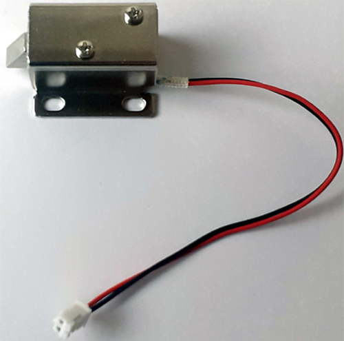
Solenoid Lock
A solenoid lock works on the electronic-mechanical locking mechanism. This type of lock has a slug with a slanted cut and a good mounting bracket. When the power is applied, DC creates a magnetic field that moves the slug inside and keeps the door in the unlocked position. The slug will retain its position until the power is removed. When the power is disconnected the slug moves outside and locks the door. It doesn’t use any power in a locked state. To drive the solenoid lock you would need a power source that can give 12V @ 500mA.
Circuit Diagram
Circuit Diagram for Solenoid Door Lock using Arduino is given below.

Connections between Arduino and RFID are given in the table below. The positive pin of the buzzer is connected to digital pin 4 of Arduino, and the GND pin is connected to the ground pin of Arduino. A 10K resistor is used between the VCC and OUT pin of the Hall Effect sensor. The solenoid lock is connected to Arduino through the relay module.
| RFID Pin | Arduino Uno Pin |
| SDA | Digital 10 |
| SCK | Digital 13 |
| MOSI | Digital 11 |
| MISO | Digital 12 |
| IRQ | Unconnected |
| GND | GND |
| RST | Digital 9 |
| 3.3V | 3.3V |
| Hall Effect Sensor Pin | Arduino Uno Pin |
| 5V | 5V |
| GND | GND |
| OUT | 3 |
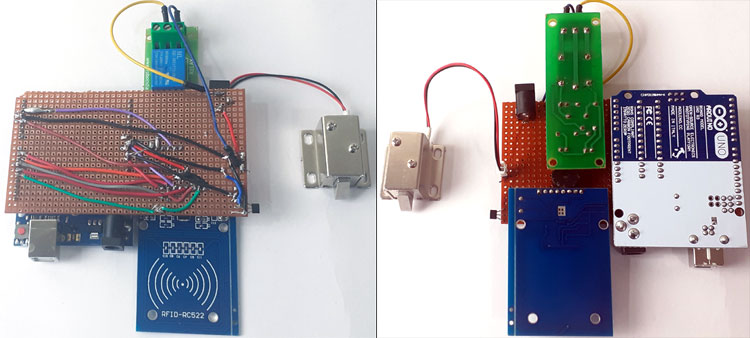
After soldering all the components on the perf board according to the circuit diagram, it looks like the below image:
Code Explanation
Complete code for this Arduino solenoid lock is given at the end of the document. Here we are explaining this code step by step for better understanding.
Start the code by including all the required libraries. Here it only requires two libraries, one for SPI communication between Arduino and RFID, and second for the RFID module. Both the libraries can be downloaded from the links given below:
Now define the pins for Buzzer, Solenoid Lock and RFID Module
int Buzzer = 4;
const int LockPin = 2;
#define SS_PIN 10
#define RST_PIN 9
Then define the Lock pin and Buzzer pin as an output, and Hall Effect sensor pin as input and initiate the SPI communication.
pinMode(LockPin, OUTPUT); pinMode(Buzzer, OUTPUT); pinMode(hall_sensor, INPUT); SPI.begin(); // Initiate SPI bus mfrc522.PCD_Init(); // Initiate MFRC522
Inside the void loop, read the hall sensor values, and when it becomes low, close the door.
state = digitalRead(hall_sensor);
  Serial.print(state);
  delay(3000);
  if(state==LOW){
   digitalWrite(LockPin, LOW);
   Serial.print("Door Closed");
   digitalWrite(Buzzer, HIGH);
   delay(2000);
   digitalWrite(Buzzer, LOW);}
Inside the void loop function, it will check if a new RFID card is present, and if a new card is present, then it will check the UID of the card. For a valid card, it will open the lock; otherwise, it will print ‘You are not authorized.’ Complete working is shown in the video given at the end.
if ( ! mfrc522.PICC_IsNewCardPresent())
  {
    return;
  }
  // Select one of the cards
  if ( ! mfrc522.PICC_ReadCardSerial())
  {
    return;
  }
  //Show UID on serial monitor
  String content= "";
  byte letter;
  for (byte i = 0; i < mfrc522.uid.size; i++)
  {
     content.concat(String(mfrc522.uid.uidByte[i] < 0x10 ? " 0" : " "));
     content.concat(String(mfrc522.uid.uidByte[i], HEX));
  }
  Serial.println();
  Serial.print("Message : ");
  content.toUpperCase();
  if (content.substring(1) == "60 4E 07 1E" ) //change here the UID of the card/cards that you want to give access
  {
    digitalWrite(LockPin, HIGH);
    Serial.print("Door Unlocked");
    digitalWrite(Buzzer, HIGH);
    delay(2000);
    digitalWrite(Buzzer, LOW);
  }
  else
  {
   Serial.println("You are not Authorised");
   digitalWrite(Buzzer, HIGH);
   delay(2000);
   digitalWrite(Buzzer, LOW);
  }
}
Testing the RFID Solenoid Lock
Once you are ready with the code and hardware, you can start testing the Solenoid Door Lock project. Here we have soldered all the components on the perf board so that it can be mounted on the door easily.
So to test it, mount the perf board on the door frame and magnet on the door so that it can detect the door movement. The below picture shows how the magnet and Hall sensors are fixed on the door.
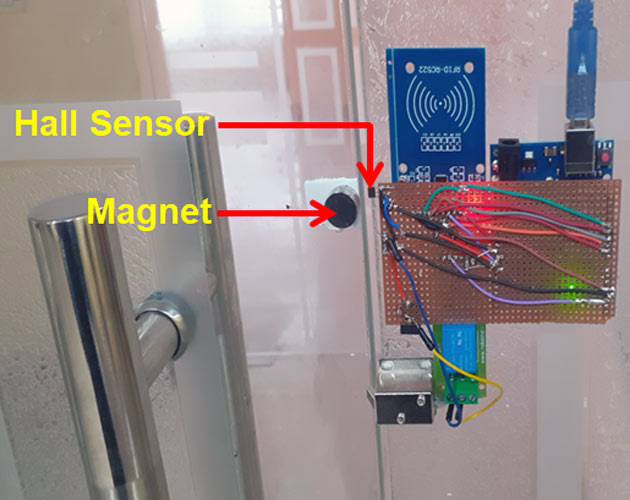
Now scan your authorized RFID card to open the door lock. The solenoid door lock will remain open until the Hall Effect sensor output is high. Now when the door again reaches near to the Hall sensor while closing, Hall Effect sensor status will change to Low due to the magnetic field (generated by the magnet attached at the door), and the lock will be closed again.
Instead of using the Hall Effect sensor, you can introduce a delay to keep the door open for a defined time.
Complete code and working video are given below. Also, check other types of door lock using different technologies.
Complete Project Code
#include <SPI.h>

#include <MFRC522.h>

int hall_sensor = 3;

int state,lockread;

int Buzzer = 4;

const int LockPin = 2;

#define SS_PIN 10

#define RST_PIN 9

MFRC522 mfrc522(SS_PIN, RST_PIN);   // Create MFRC522 instance.

void setup()

{

  Serial.begin(9600);   // Initiate a serial communication

  pinMode(LockPin, OUTPUT);

  pinMode(Buzzer, OUTPUT);

  pinMode(hall_sensor, INPUT);

  SPI.begin();      // Initiate  SPI bus

  mfrc522.PCD_Init();   // Initiate MFRC522

  //Serial.println("Approximate your card to the reader...");

  // Serial.println();

  digitalWrite(LockPin, LOW);

}

void readsensor()

{

 lockread = digitalRead(LockPin);

 state = digitalRead(hall_sensor);

 //Serial.print(lockread);

 //Serial.print(state);

 // delay(2000);

}

void loop()

{

  readsensor();

  sensor();

  // Look for new cards

  if ( ! mfrc522.PICC_IsNewCardPresent())

  {

    return;

  }

  // Select one of the cards

  if ( ! mfrc522.PICC_ReadCardSerial())

  {

    return;

  }

  //Show UID on serial monitor

  String content= "";

  byte letter;

  for (byte i = 0; i < mfrc522.uid.size; i++)

  {

     content.concat(String(mfrc522.uid.uidByte[i] < 0x10 ? " 0" : " "));

     content.concat(String(mfrc522.uid.uidByte[i], HEX));

  }

  //Serial.println();

  //Serial.print("Message : ");

  content.toUpperCase();

  if (content.substring(1) == "60 4E 07 1E" ) //change here the UID of the card/cards that you want to give access

  {

    digitalWrite(LockPin, HIGH);

    Serial.print("Door Unlocked");

    digitalWrite(Buzzer, HIGH);

    delay(2000);

    digitalWrite(Buzzer, LOW);

    sensor();

    }

  else

  {

   Serial.println("You are not Authorised");

   digitalWrite(Buzzer, HIGH);

   delay(2000);

   digitalWrite(Buzzer, LOW);

  }

}

void sensor()

{

 readsensor();

 if (lockread == HIGH){

      readsensor();

      if(state==LOW){

      digitalWrite(LockPin, LOW);

      Serial.print("Door Closed");

      digitalWrite(Buzzer, HIGH);

      delay(2000);

      digitalWrite(Buzzer, LOW);

    }

  }

 }

i need help for authorised card to open door