
Knowing the whereabouts of a particular object/person has always been comforting. Today, GPS is being extensively used in asset management applications like Vehicle Tracking, Fleet Tracking, Asset monitoring, Person tracking, Pet Tracker etc. For any tracking device the primary design consideration will be about its battery expectancy and monitoring range. Considering both, LoRa seems to be perfect choice since it has very low power consumption and can operate on long distances. So, in this tutorial we will build GPS tracking system using LoRa, the system will consist of a Transmitter which will read the location information from the NEO-6M GPS module and transmit it wireless over Lora. The receiver part will receive the information and display it on a 16x2 LCD display. If you are new to LoRa then learn about LoRa and LoRaWAN Technology and how it can be interfaced with Arduino before proceeding further.
To keep things simple and cost-effective for this project we will not be using a LoRa gateway. Instead will perform peer to peer communication between the transmitter and receiver. However, if you want a global range you can replace the receiver with a LoRa Gateway. Also since I am from India we will be using the 433MHz LoRa module which is legal ISM band here, hence you might have to select a module based on your country. That being said, let’s get started…
Materials Required
- Arduino Lora Shield – 2Nos (PCB design available for download)
- Arduino Uno – 2Nos
- SX1278 433MHz LoRa Module – 2
- 433MHz Lora Antenna
- NEO-6M GPS Module
- LCD Display Module
- Connecting wires
Arduino LoRa Shield
To make building things with LoRa easier, we have designed a LoRa Arduino Shield for this Project. This shield consists of the SX1278 433MHz with a 3.3V regulator designed using LM317 Variable regulator. The Shield will directly sit on top of Arduino providing it LoRa capabilities. This LoRa Shield will come in handy when you have to deploy LoRa sensing nodes or to create a LoRa mesh network. The complete circuit diagram for the LoRa Arduino Shield is given below
![]()
The Shield consists of a 12V jack which when powered will be used to regulate 3.3V for the LoRa module using the LM317 regulator. It will also be used to power the Arduino UNO through Vin pin and the regulated 5V from the Arduino is used to power the LCD on the shield. The output voltage of the LM317 is fixed to be 3.3V using the resistor R1 and R2 respectively, the value of these resistors can be calculated using the LM317 Calculator.
![]()
Since the LoRa module consumes very low power, it can also be powered directly from the 3.3V pin of Arduino, but we have used an external regulator design since LM317 is more reliable than the on-board voltage regulator. The shield also has a potentiometer which can be used to adjust the brightness of the LCD. The connection of LoRa module with Arduino is similar to what we did in our previous tutorial of Interfacing Arduino with Lora.
Fabricating PCB for LoRa Shield
Now that our circuit is ready, we can proceed with designing our PCB. I opened by PCB design software and began forming my tracks. Once the PCB design was complete my board looked something like this shown below
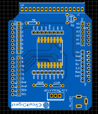
You can also download the design files in GERBER format and fabricate it to get your boards. The Gerber file link is given below
Download Gerber File for Arduino LoRa Shield
Now, that our Design is ready it is time to get them fabricated. To get the PCB done is quite easy, simply follow the steps below
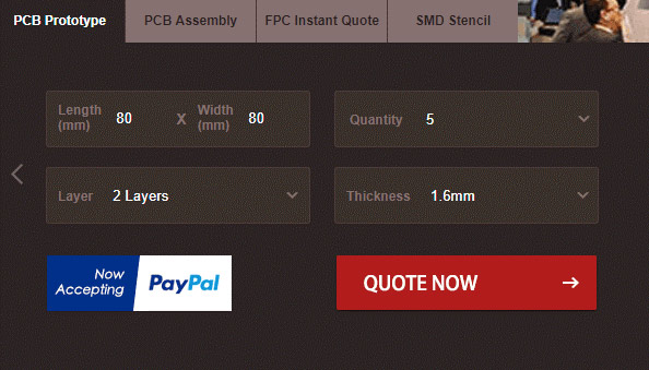
Step 1: Get into www.pcbgogo.com, sign up if this is your first time. Then, in the PCB Prototype tab enter the dimensions of your PCB, the number of layers and the number of PCB you require. Assuming the PCB is 80cm×80cm you can set the dimensions as shown below.
Step 2: Proceed by clicking on the Quote Now button. You will be taken to a page where to set few additional parameters if required like the material used track spacing etc. But mostly the default values will work fine. The only thing that we have to consider here is the price and time. As you can see the Build Time is only 2-3 days and it just costs only $5 for our PSB. You can then select a preferred shipping method based on your requirement.
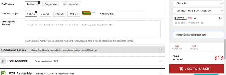
Step 3: The final step is to upload the Gerber file and proceed with the payment. To make sure the process is smooth PCBGOGO verifies if your Gerber file is valid before proceeding with the payment. This way you can sure that your PCB is fabrication friendly and will reach you as committed.
Assembling the PCB
After the board was ordered, it reached me after some days though courier in a neatly labeled well-packed box and like always the quality of the PCB was awesome.
I turned on my soldering rod and started assembling the Board. Since the Footprints, pads, vias and silkscreen are perfectly of the right shape and size I had no problem assembling the board. Once the soldering was complete the board looked like this below, as you can see it fits snug on my Arduino Uno Board.
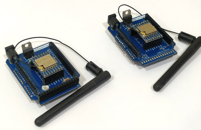
Since our project has an Arduino LoRa transmitter and a Arduino LoRa receiver we will need two shields one for receiver and the other for transmitter. So I proceeded with soldering another PCB, both the PCB with LoRa module and LCD is shown below.
As you can see only the receiver LoRa shied (left one) has an LCD connected it, the transmitter side only consists of the LoRa module. We will further connect a GPS module to the transmitter side as discussed below.
Connecting GPS module to LoRa Transmitter
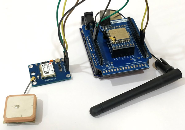
The GPS module used here is the NEO-6M GPS module, the module can operate on very low power with a small form factor making it suitable for tracking applications. However there are many other GPS modules available which we have used previously in different kind of vehicle tracking and location detection applications.
The module operates in 5V and communicates using Serial communication at 9600 baud rate. Hence we power the module to +5V pin of Arduino and connect the Rx and Tx pin to digital pin D4 and D3 respectively as shown below
The pins D4 and D3 will be configured as software serial pins. Once powered the NEO-6M GPS module will look for satellite connection and the will automatically output all the information serially. This output data will be in the NMEA sentence format which stands for National Marine Electronics Association and is the standard format for all GPS devices. To learn more about using GPS with Arduino, follow the link. This data will be large and most time we have to phrase it manually to obtain the desired result. Lucky for us there is a library called TinyGPS++ which does all the heavy lifting for us. You also have to add the LoRa library if you have not done it yet. So let’s download both the library from below link
Download TinyGPS++ Arduino Library
The link will download a ZIP file which can then be added to the Arduino IDE by following the command Sketch -> Include Library -> Add.ZIP library. Once you are ready with the hardware and library we can proceed with Programming our Arduino boards.

Programming Arduino LoRa as GPS Transmitter
As we know the LoRa is a transceiver device, meaning it can both send and receive information. However in this GPS tracker project we will use one module as transmitter to read the co-ordinate information from GPS and send it, while the other module as a receiver which will receive the GPS co-ordinate values and print it on the LCD. The program for both the Transmitter and Receiver module can be found at the bottom of this page. Make sure you have installed the libraries for GPS module and LoRa module before proceeding with the code. In this section we will look at the transmitter code.
Like always we begin the program by adding the required libraries and pins. Here the SPI and LoRa library is used for LoRa communication and the TinyGPS++ and SoftwareSerial library is used for GPS communication. The GPS module in my hardware is connected to pin 3 and 4 and hence we also define that as follows
#include <SPI.h>
#include <LoRa.h>
#include <TinyGPS++.h>
#include <SoftwareSerial.h>
// Choose two Arduino pins to use for software serial
int RXPin = 3;
int TXPin = 4;
Inside the setup function we begin the serial monitor and also initialize the software serial as “gpsSerial” for communication with our NEO-6M GPS module. Also note that I have used 433E6 (433 MHz) as my LoRa operating frequency you might have to change it based on the type of module you are using.
void setup() {
  Serial.begin(9600);
   gpsSerial.begin(9600);
  while (!Serial);
  Serial.println("LoRa Sender");
  if (!LoRa.begin(433E6)) {
    Serial.println("Starting LoRa failed!");
    while (1);
  }
  LoRa.setTxPower(20);
}
Inside the loop function we check if the GPS module is putting out some data, if yes then we read all the data and phrase it using the gps.encode function. Then we check if we have received a valid location data using the gps.location.isValid() function.
while (gpsSerial.available() > 0)
    if (gps.encode(gpsSerial.read()))
        if (gps.location.isValid())
  {
If we have received a valid location we can then begin transmitting the latitude and longitude values. The function gps.location.lat() gives the latitude co-ordinate and the function gps.location.lng() gives the longitude co-ordinate. Since we will be printing them on the 16*2 LCD we have to mention when to shit to second line, hence we use the keyword “c” to intimate the receiver to print the following information on line 2.
    LoRa.beginPacket();
    LoRa.print("Lat: ");
    LoRa.print(gps.location.lat(), 6);
    LoRa.print("c");
    LoRa.print("Long: ");
    LoRa.print(gps.location.lng(), 6);
    Serial.println("Sent via LoRa");
    LoRa.endPacket();
Programming Arduino LoRa as GPS receiver
The transmitter code is already sending the value of latitude and longitude co-ordinates, now the receiver has to read these values and print on the LCD. Similarly here we add the library for LoRa module and LCD display and define to which pins the LCD is connected to and also initialize the LoRa module like before.
#include <SPI.h> //SPI Library
#include <LoRa.h> //LoRa Library
#include <LiquidCrystal.h> //Library for LCD

const int rs = 8, en = 7, d4 = 6, d5 = 5, d6 = 4, d7 = 3; //Mention the pin number for LCD connection
LiquidCrystal lcd(rs, en, d4, d5, d6, d7);//Initialize LCD method

void setup() {
  Serial.begin(9600); //Serial for Debugging

  lcd.begin(16, 2); //Initialise 16*2 LCD
  lcd.print("Arduino LoRa"); //Intro Message line 1
  lcd.setCursor(0, 1);
  lcd.print("Receiver"); //Intro Message line 2
  delay(2000);

  if (!LoRa.begin(433E6)) { //Operate on 433MHz
    Serial.println("Starting LoRa failed!");
    lcd.print("LoRa Failed");
    while (1);
  }
}
Inside the loop function we listen for data packets form the transmitter LoRa module and the size of it using the LoRa.parsePacket() function and store it in “packetSize” variable. If packets are received then we proceed with reading them as characters and print them on the LCD. The program also checks if the LoRa module is sending the keyword “c”, if yes then prints the remaining information on the second line.
if (packetSize) {     // If packet received
    Serial.print("Received packet '");
    lcd.clear();

    while (LoRa.available()) {
      char incoming = (char)LoRa.read();
      if (incoming == 'c')
      {
        lcd.setCursor(0, 1);
      }
      else
      {
        lcd.print(incoming);
      }
    }
Arduino LoRa GPS Tracker Working
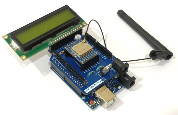
Once the hardware and program is ready we can upload both the codes in the respective Arduino modules and power them using a 12V adapter or USB cable. When the Transmitter is powered you can notice the blue LED on the GPS module blinking, this indicates that the module is looking for satellite connection to get co-ordinates. Meanwhile the Receiver module will power on and display a welcome message on the LCD screen. Once the transmitter sends the information the receiver module will display it on its LCD as shown below
![]()
Now you can move around with the transmitter GPS module and you will notice the receiver updating its location. To know where exactly the transmitter module is you can read the latitude and longitude values displayed on the LCD and enter it into Google maps to get the location on map as shown below.
![]()
The complete working can also be found in the video given at the bottom of this page. Hope you understood the tutorial and enjoyed building something useful with it. If you have any doubts you can leave them in the comment section below or use our forums for other technical queries.
Complete Project Code
Lora Sender Code
#include <SPI.h>
#include <LoRa.h>
#include <TinyGPS++.h>
#include <SoftwareSerial.h>
// Choose two Arduino pins to use for software serial
int RXPin = 3;
int TXPin = 4;
// Create a TinyGPS++ object
TinyGPSPlus gps;
SoftwareSerial gpsSerial(RXPin, TXPin);
void setup() {
  Serial.begin(9600);
   gpsSerial.begin(9600);
  while (!Serial);
  Serial.println("LoRa Sender");
  if (!LoRa.begin(433E6)) {
    Serial.println("Starting LoRa failed!");
    while (1);
  }
  LoRa.setTxPower(20);

}
void loop() {

 while (gpsSerial.available() > 0)
    if (gps.encode(gpsSerial.read()))

        if (gps.location.isValid())
  {
    Serial.println("Sending to LoRa");
    LoRa.beginPacket();
    LoRa.print("Lat: ");
    LoRa.print(gps.location.lat(), 6);
    LoRa.print("c");
    LoRa.print("Long: ");
    LoRa.print(gps.location.lng(), 6);
    Serial.println("Sent via LoRa");
    LoRa.endPacket();
  }
}

Lora Receiver Code
/*Program to receive the value of temperature and Humidity via LoRa and prin on LCD
 *Dated: 24-06-2019
 */

#include <SPI.h> //SPI Library
#include <LoRa.h> //LoRa Library
#include <LiquidCrystal.h> //Library for LCD
const int rs = 8, en = 7, d4 = 6, d5 = 5, d6 = 4, d7 = 3; //Mention the pin number for LCD connection
LiquidCrystal lcd(rs, en, d4, d5, d6, d7);//Initialize LCD method
void setup() {
  Serial.begin(9600); //Serial for Debugging

  lcd.begin(16, 2); //Initialise 16*2 LCD
  lcd.print("Arduino LoRa"); //Intro Message line 1
  lcd.setCursor(0, 1);
  lcd.print("Receiver"); //Intro Message line 2
  delay(2000);

  if (!LoRa.begin(433E6)) { //Operate on 433MHz
    Serial.println("Starting LoRa failed!");
    lcd.print("LoRa Failed");
    while (1);
  }
}
void loop() {
  int packetSize = LoRa.parsePacket();

  if (packetSize) {     // If packet received
    Serial.print("Received packet '");
    lcd.clear();
    while (LoRa.available()) {
      char incoming = (char)LoRa.read();
      if (incoming == 'c')
      {
        lcd.setCursor(0, 1);
      }
      else
      {
        lcd.print(incoming);
      }

    }
  }
}
Comments
how do i send gps data to things network instead of showing it on LCD>?

I am unable to find relevent antenna for 433MHz LoRa module. Can you please provide me the link to purchase LoRa Antenna???