

A Rotary encoder is an input device which helps the user to interact with a system. It looks more like a Radio potentiometer but it outputs a train of pulses which makes its application unique. When the knob of the Encoder is rotated it rotates in form of small steps which helps it to be used for stepper/Servo motor controlling, navigating through a sequence of menu and Increasing/decreasing the value of a number and much more.
In this article we will learn about the different types of Rotary Encoders and how it work. We will also interface it with Arduino and control the value of an integer by rotating the Encoder and display its value on a 16*2 LCD screen. At the end of this tutorial you will be comfortable with using an Rotary Encoder for your projects. So let’s get started...
Materials Required
- Rotary Encoder (KY-040)
- Arduino UNO
- 16*2 Alphanumeric LCD
- Potentiometer 10k
- Breadboard
- Connecting wires
How does a Rotary Encoder Work?
A Rotary Encoder is an electromechanical transducer, meaning it converts mechanical movements into electronic pulses. It consists of a knob which when rotates will move step by step and produce a sequence of pulse trains with pre-defined width for each step. There are many types of Encoders each with its own working mechanism, we will learn about the types later but for now let us concentrate only on the KY040 Incremental Encoder since we are using it for our tutorial.
The internal mechanical structure for the Encoder is shown below. It basically consists of a circular disc (grey colour) with conductive pads (copper colour) placed on top of this circular disc. These conductive pads are placed at an equal distance as shown below. The Output pins are fixed on top of this circular disc, in such a way that when the knob is rotates the conductive pads get in contact with the output pins. Here there are two output pin, Output A and Output B as shown in the figure below.
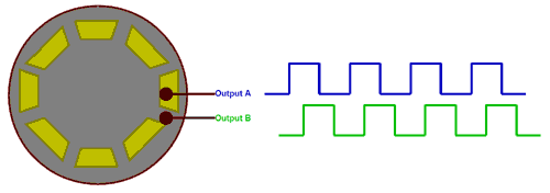
The output waveform produced by the Output pin A and Output B is show in blue and green colour respectively. When the conductive pad is directly under the pin it goes high resulting it on time and when the conductive pad moves away the pin goes low resulting in off time of the waveform shown above. Now, if we count the number of pulses we will be able to determine how many steps the Encoder has been moved.
Now the question may arise that, why do we need two pulse signals when one is enough to count the number of steps taken while rotating the knob. This is because we need to identify in which direction the knob has been rotated. If you take a look at the two pulses you can notice that they both are 90° out of phase. Hence when the knob is rotated clockwise the Output A will go high first and when the knob is rotated anti-clockwise the Output B will go high first.
Types of Rotary Encoder
There are many types of rotary encoder in the market the designer can choose one according to his application. The most common types are listed below
- Incremental Encoder
- Absolute Encoder
- Magnetic Encoder
- Optical Encoder
- Laser Encoder
These encoders are classified based on the Output signal and sensing technology, the Incremental Encoder and Absolute Encoders are classified based on Output signal and the Magnetic, Optical and Laser Encoder are classified based on Sensing Technology. The Encoder used here is an Incremental type Encoder.
KY-040 Rotary Encoder Pinout and description
The pinouts of the KY-040 Incremental type rotary encoder is shown below
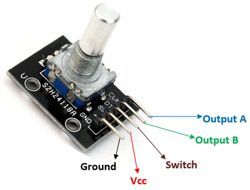
The first two pins (Ground and Vcc) is used to power the Encoder, typically +5V supply is used. Apart from rotating the knob in clock wise and anti-clockwise direction, the encoder also has a switch (Active low) which can be pressed by pressing the knob inside. The signal from this switch is obtained through the pin 3 (Switch). Finally it has the two output pins which produce the waveforms as already discussed above. Now let us learn how to interface it with Arduino.
Arduino Rotary Encoder Circuit Diagram
The complete circuit diagram for Interfacing Rotary Encoder with Arduino is shown in the picture below

The Rotary Encoder has 5 pins in the order shown in the label above. The first two pins are Ground and Vcc which is connected to the Ground and +5V pin of the Arduino. The switch of the encoder is connected to digital pin D10 and is also pulled high though a 1k resistor. The two output pins are connected to D9 and D8 respectively.
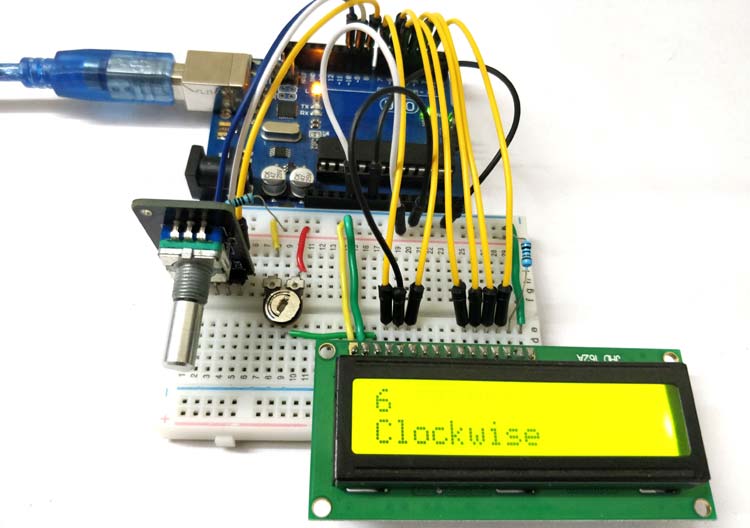
To display the value of the variable which will be increased or decreased by rotating the Rotary encoder we need a display module. The one used here is commonly available 16*2 Alpha numeric LCD display. We have connected the display to be operated in 4-bit mode and have powered it using the +5V pin of Arduino. The Potentiometer is used to adjust the contrast of the LCD display. If you want to know more about Interfacing LCD display with Arduino follow the link. The complete circuit can be built on top of a breadboard, my looked something like this below once all the connections were done.

Programming your Arduino for Rotary Encoder
It is fairly easy and straight forward to program the Arduino board for interfacing a Rotary Encoder with it if you had understood the working principle of a Rotary Encoder. We simply have to read the number of pulse to determine how many turns the encoder has made and check which pulse went high first to find in which direction the encoder was rotated. In this tutorial we will display the number that is being increment or decrement on the first row of the LCD and the direction of the Encoder in the second line. The complete program for doing the same can be found at the bottom of this page with a Demonstration Video, it does not require any library. Now, let’s split the program into small chunks to understand the working.
Since we have used an LCD display, we include the Liquid crystal library which is by default present in the Arduino IDE. Then we define pins for connecting LCD with Arduino. Finally we initialise the LCD display on those pins.
#include <LiquidCrystal.h> //Default Arduino LCD Library is included
const int rs = 7, en = 6, d4 = 5, d5 = 4, d6 = 3, d7 = 2; //Mention the pin number for LCD connection
LiquidCrystal lcd(rs, en, d4, d5, d6, d7);
lcd.begin(16, 2); //Initialise 16*2 LCD
Next inside the setup function, we display an introductory message on the LCD screen, and then wait for 2 seconds so that that message is user readable. This is to ensure that the LCD is working properly.
  lcd.print(" Rotary Encoder "); //Intro Message line 1
  lcd.setCursor(0, 1);
  lcd.print("  With Arduino  "); //Intro Message line 2

  delay(2000);
  lcd.clear();
The Rotary encoder has three output pins which will be an INPUT pins for the Arduino. These three pins are the Switch, Output A and Output B respectively. These are declared as Input using the pinMode function as shown below.
//pin Mode declaration
  pinMode (Encoder_OuputA, INPUT);
  pinMode (Encoder_OuputB, INPUT);
  pinMode (Encoder_Switch, INPUT);
Inside the void setup function, we read the status of the output A pin to check the last status of the pin. We will then use this information to compare with the new value to check which pin (Output A or Output B) has gone high.
Previous_Output = digitalRead(Encoder_OuputA); //Read the inital value of Output A
Finally inside the main loop function, we have to compare the value of Output A and Output B with the Previous Output to check which one goes high first. This can be done by simply comparing the value of current output of A and B with the previous output as shown below.
   if (digitalRead(Encoder_OuputA) != Previous_Output)
   {
     if (digitalRead(Encoder_OuputB) != Previous_Output)
     {
       Encoder_Count ++;
       lcd.clear();
       lcd.print(Encoder_Count);
       lcd.setCursor(0, 1);
       lcd.print("Clockwise");
     }
In the above code the second if condition gets executed if Output B has changed from the previous output. In that case the value of the encoder variable is incremented and the LCD displays that the encoder is rotated in clockwise direction. Similarly if that if condition fails, in the subsequent else condition we decrement the variable and display that the encoder is rotated in the anticlockwise direction. The code for the same is shown below.
     else
     {
       Encoder_Count--;
       lcd.clear();
       lcd.print(Encoder_Count);
       lcd.setCursor(0, 1);
       lcd.print("Anti - Clockwise");
     }
   }
Finally, at the end of the main loop we have to update the previous output value with the current output value so that the loop can be repeated with the same logic. The following code does the same
Previous_Output = digitalRead(Encoder_OuputA);
Another optional thing is to check if the switch on the Encoder is pressed. This can be monitored by checking the switch pin on the rotary coder. This pin is a active low pin, meaning that it will go low when the button is pressed. If not pressed the pin stays high, we also have used a pull up resistor to make sure the stays high when switch is not pressed thus avoiding floating point condition.
   if (digitalRead(Encoder_Switch) == 0)
   {
     lcd.clear();
     lcd.setCursor(0, 1);
     lcd.print("Switch pressed");
   }
Working of Rotary Encoder with Arduino
Once the hardware and code is ready, just upload the code to the Arduino board and power up the Arduino Board. You can either power it through the USB cable or use a 12V adapter. When powered the LCD should display the intro message and then get blank. Now rotate the rotary encoder and you should see the value begin incremented or decremented based on the direction you rotate. The second line will show you if the encoder is being rotated in clockwise or anti-clockwise direction. The picture below shows the same
Also when the button is pressed, the second line will display that the button is pressed. The complete working can be found in the video below. This is just a sample program to interface the Encoder with Arduino and check if it is working as expected. Once you get here you should be able to use the encoder for any of your projects and program accordingly.
Hope you have understood the tutorial and things worked as it is supposed to. If you have any problems use the comment section or the forums for technical help.
Complete Project Code
/*

 * Interfacing Rotary Encoder with Arduino

 * Dated: 6-7-2018

 * Website: www.circuitdigest.com

 *

 * Power LCD and Rotary encoder from the +5V pin of Arduino

 * LCD RS -> pin 7

 * LCD EN -> pin 6

 * LCD D4 -> pin 5

 * LCD D5 -> pin 4

 * LCD D6 -> pin 3

 * LCD D7 -> pin 2

 * Encoder Switch -> pin 10

 * Encoder Output A -> pin 9

 * Encoder Output B -> pin 8

 */
int Encoder_OuputA  = 9;

int Encoder_OuputB  = 8;

int Encoder_Switch = 10;
int Previous_Output;

int Encoder_Count;

#include <LiquidCrystal.h>  //Default Arduino LCD Librarey is included
const int rs = 7, en = 6, d4 = 5, d5 = 4, d6 = 3, d7 = 2; //Mention the pin number for LCD connection

LiquidCrystal lcd(rs, en, d4, d5, d6, d7);
void setup() {

  lcd.begin(16, 2); //Initialise 16*2 LCD
  lcd.print(" Rotary Encoder "); //Intro Message line 1

  lcd.setCursor(0, 1);

  lcd.print("  With Arduino  "); //Intro Message line 2
  delay(2000);

  lcd.clear();
//pin Mode declaration

  pinMode (Encoder_OuputA, INPUT);

  pinMode (Encoder_OuputB, INPUT);

  pinMode (Encoder_Switch, INPUT);
  Previous_Output = digitalRead(Encoder_OuputA); //Read the inital value of Output A

}
void loop() {

   //aVal = digitalRead(pinA);


   if (digitalRead(Encoder_OuputA) != Previous_Output)

   {

     if (digitalRead(Encoder_OuputB) != Previous_Output)

     {

       Encoder_Count ++;

       lcd.clear();

       lcd.print(Encoder_Count);

       lcd.setCursor(0, 1);

       lcd.print("Clockwise");

     }

     else

     {

       Encoder_Count--;

       lcd.clear();

       lcd.print(Encoder_Count);

       lcd.setCursor(0, 1);

       lcd.print("Anti - Clockwise");

     }

   }
   Previous_Output = digitalRead(Encoder_OuputA);
   if (digitalRead(Encoder_Switch) == 0)

   {

     lcd.clear();

     lcd.setCursor(0, 1);

     lcd.print("Switch pressed");

   }

}
Comments
interfacing-rotary-encoder-with-arduino
Neat! Found an encoder (1 of an order of 5) made backwards.

thanks for showing some example and carrying on to send for me the new vision one to update old encoder