
Short-circuit is unintended connection between two terminals which are supplying power to the load. It can happen both in AC or DC circuit, if it is an AC supply then short circuit can trip the power supply of whole area, but there are fuses and overload protection circuits at many levels, from the power station to the house. And if it is a DC source like battery then it can heat up the battery and battery will be discharged very quickly. In some cases battery can be exploded. There are lot of ways to protect circuit from short-circuit and many types of fuses are available for overload protection.
We are going to design and study a simple low voltage Short-circuit protection circuit for DC voltage. The circuit is designed with a purpose to run microcontroller circuit safely and can protect it from damaging due to short-circuit in other part of the circuitry.
Components required
- SK100B PNP transistor - 1Nos.
- BC547B NPN transistor - 1Nos.
- 1kΩ Resistor - 1Nos.
- 10kΩ Resistor - 1Nos.
- 330Ω Resistor - 2Nos.
- 470Ω Resistor - 1Nos.
- Power supply 6VDC - 1Nos.
- Breadboard - 1Nos.
- Connecting wires - As per requirement
SK100B PNP Transistor
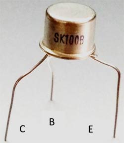
Starting from the notch of the transistor is Emitter, middle is base and last is Collector
- Emitter - E
- Base - B
- Collector - C
BC547B NPN transistor
![]()
Short Circuit Protection Circuit
A common example of short-circuit is when positive and negative terminal of a battery are connected together with a low-resistance conductor, like a wire. In this condition, battery can set to fire and can even explode. That’s what happens with mobile batteries in mobiles at many times.
To avoid this short circuit condition, Short-circuit Protection Circuit is used. Short-circuit Protection Circuit will divert the flow of current or break the contact between the circuit and the power source.
Sometimes we experience power failure with a sudden spark while using some faulty home appliances like oven, iron, etc, then. The reason behind this is that, somewhere there is some excess current flows through some circuit inside that faulty appliance. This may lead to shock or could fire up the house if not protected. So a fuse or circuit breaker is used in order to avoid such damage. In such condition circuit breaker or fuse disconnects the main supply to the house. A fuse breaker circuit is also a form of short-circuit protection circuit, in which a low resistance wire is used which melts and disconnects the main power supply to house whenever there is excess current pass through it.
So here we are going to study and design circuit to avoid the damage due to short-circuit in it.
Circuit Diagram


Working of Short Circuit Protection Circuit
A simple low power DC Short-circuit Protection Circuit is shown above which consists two transistor circuits, one is BC547 NPN transistor circuit and other is SK100B PNP transistor circuit. The input is provided to the circuit using a 5V DC Power supply, which can be either provided by some battery or using transformer.
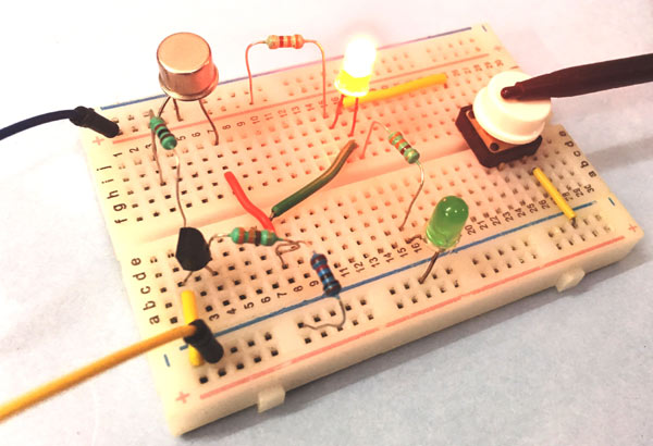
The working of the circuit is simple, when Green LED D1 glows means the circuit is functioning normally and there is no risk of damage. The Red LED D2 is expected to glow only when there is short circuit.
When the power supply is turned ON, transistor Q1 gets biased and starts conducting and LED D1 gets turns ON. During this time Red LED D2 remains off as there is no Short-circuit.
The glowing of Green LED D1 also indicates that the supply voltage and output voltage is approximately equal.
In our stimulation circuit we have generated a ‘short’ using a switch at the output. When the ‘short’ occurs the output voltage drops to 0V and Q1 stops conducting as its base voltage is 0V. Transistor Q2 also stops conducting as its collector voltage also dropped to 0V.
So now current is started flowing through RED led D2 and pass through the ground via the short circuit path (through the switch). That makes Red LED D2 starts conducting as it is forward biased and indicates that a short has been detected and the current is diverted through the RED LED D2 instead of damaging the entire circuit.
Comments
App development
Hello, and thank you for your wonderful effort for the benefit of us beginners in electronics.
I would suggest that you create an app regarding this, as I could not find one on play store.
Good morning sir. How can
Good morning sir. How can this circuit be modified for use in 12v appliance? I'm a novice in electronics and want to build it. Thanks.
Sir, in our country it is…
Sir, in our country it is difficult to find sk100 or ck00 nowadays. could you please give me a suggestion for it?
Thank you.

Good and it's very useful,this generation students use more this type of informations.