

The field of Robotics, Artificial Intelligence and Machine Learning is evolving rapidly that it is sure to change the lifestyle of mankind in near future. Robots are thought to understand and interact with the real world through sensors and machine learning processing. Image recognition is one of the popular way in which the robots are thought to understand objects by looking at the real world through a camera just like we do. In this project, let use the power of Raspberry Pi to build a Robot that could track ball and follow it just like the robots that plays football.
OpenCV is a very famous and open source tool that is used for Image processing, but in this tutorial to keep things simple we are using the Processing IDE. Since processing for ARM has also released the GPIO library for processing we will not have to shift between python and processing anymore to work with Raspberry Pi. Sounds cool right? So let us get started.
Hardware Required:
- Raspberry Pi
- Camera module with ribbon cable
- Robot Chassis
- Gear motors with wheel
- L293D motor driver
- Power bank or any other portable power source
Programming Requirement:
- Monitor or other display for Raspberry pi
- Key board or mouse for Pi
- Processing ARM software
Note: It is mandatory to have a display connected to Pi through wires during programming because only then the camera’s video can be viewed
Setting up Processing on Raspberry Pi:
As told earlier we will be using the processing environment to Program our Raspberry Pi and not the default way of using python. So, follow the steps below:
Step 1:- Connect your Raspberry Pi to your monitor, keyboard and mouse and turn it on.
Step 2:- Make sure you Pi is connected to an active internet connection because we are about to download few things.
Step 3:- Click on Processing ARM, to download the processing IDE for Raspberry Pi. The download will be in the form of a ZIP file.
Step 4:- Once downloaded, extract the files in your ZIP folder in you preferred directory. I just extracted it on my desktop.
Step 5:- Now, open the extracted folder and click on the file named processing. It should open a window as shown below.
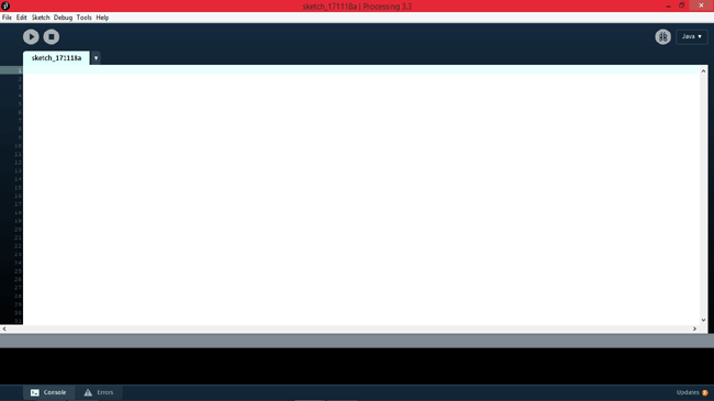
Step 6:- This is the environment where we will be typing our codes. For people who are familiar with Arduino, don’t be shocked YES the IDE does look similar to Arduino and so does the program.
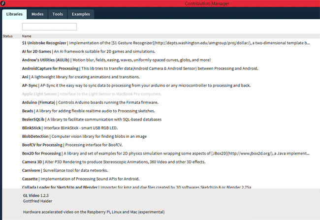
Step 7:- We need two libraries for our ball following program to work, to install then just click on Sketch -> Import Library -> Add Library. The following dialog box will open.
Step 8:- Use the top left text box to search for Raspberry Pi and hit enter, you search result should look something like this.
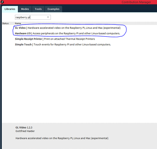
Step 9:-Search for the libraries named “GL Video” and “Hardware I/O” and click on install to install them. Make sure you install both the libraries.
Step 10:- Based on your internet the installation will take few minutes. Once done we are ready with for processing software.
Circuit Diagram:
The circuit Diagram of this Raspberry Pi Ball Tracking Project is shown below.

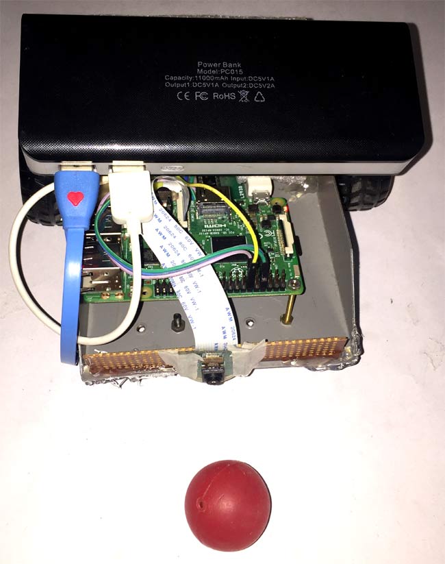
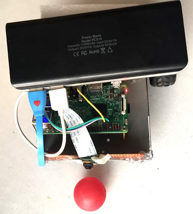
As you can see the circuit involves a PI camera, Motor Driver module and a pair of motors connected to the Raspberry pi. The complete circuit is powered by a Mobile Power bank (represented by AAA battery in the circuit above).
Since the pins details are not mentioned on the Raspberry Pi, we need to verify the pins using the below picture
To drive the Motors, we need four pins (A,B,A,B). This four pins are connected from GPIO14,4,17 and 18 respectively. The orange and white wire together forms the connection for one motor. So we have two such pairs for two motors.
The motors are connected to the L293D Motor Driver module as shown in the picture and the driver module is powered by a power bank. Make sure that the ground of the power bank is connected to the ground of the Raspberry Pi, only then your connection will work.
That is it we are done with our Hardware connection, let’s go back to our processing environment and start programming to teach our robot how to track a ball.
Raspberry Pi Ball tracking Program:
The complete Processing program of this project is given at the end of this page, which you directly use. Further just below, I have explained the working of the code so that you can use it for other similar projects.
The program concept is very simple. Although the intention of the project is to track a ball, we are actually not going to do it. We are just going to identify the ball using its colour. As we all know videos are nothing but continuous frames of pictures. So we take each picture and split it into pixels. Then we compare each pixel colour with the colour of the ball; if a match is found then we can say that we have found the ball. With this information we can also identify the position of the ball (pixel colour) on the screen. If the position is far left we move the robot to right, if the position is far right we move the robot to left so that the pixel position always stays at the centre of the screen. You can watch Computer Vision video of Daniel shiffman to get a clear picture.
As always we begin by importing the two libraries that we download. This can be done by the following two lines. The Hardware I/O library is used to access the GPIO pins of the PI directly from the processing environment, the glvideo library is used to access the Raspberry Pi camera module.
import processing.io.*;
import gohai.glvideo.*;
Inside the setup function we initialize the output pins to control the motor and also get the video from the pi camera and size it in a window of size 320 * 240.
void setup() {
  size(320, 240, P2D);
  video = new GLCapture(this);
  video.start();
  trackColor = color(255, 0, 0);
  GPIO.pinMode(4, GPIO.OUTPUT);
  GPIO.pinMode(14, GPIO.OUTPUT);
  GPIO.pinMode(17, GPIO.OUTPUT);
  GPIO.pinMode(18, GPIO.OUTPUT);
}
The void draw is like the infinite loop the code inside this loop will be execute as long as the program is terminated. If a camera source is available we read the video coming out of it
void draw() {
   background(0);
  if (video.available()) {
    video.read();
  }}
Then we begin to split the video frame into pixels. Each pixel has a value of red, green and blue. These values are stored in the variable r1, g1 and b1
  for (int x = 0; x < video.width; x ++ ) {
    for (int y = 0; y < video.height; y ++ ) {
      int loc = x + y*video.width;
      // What is current color
      color currentColor = video.pixels[loc];
      float r1 = red(currentColor);
      float g1 = green(currentColor);
      float b1 = blue(currentColor);
To detect the colour of the ball initially, we have to click on the colour. Once click the colour of the ball will be stored in variable called trackColour.
void mousePressed() {
  // Save color where the mouse is clicked in trackColor variable
  int loc = mouseX + mouseY*video.width;
  trackColor = video.pixels[loc];
}
Once we have the track colour and the current colour we have to compare them. This comparison is using the dist function. It checks how close the current colour is to the track colour.
float d = dist(r1, g1, b1, r2, g2, b2);
The value of dist will be zero for an exact match. So, if the value of dist is less than a specified value (world Record) then we assume that we have found the track colour. Then we get the location of that pixel and store it in the variable closest X and closest Y to find the location of the ball
if (d < worldRecord) {
        worldRecord = d;
        closestX = x;
        closestY = y;
      }
We also draw an ellipse around the found colour to indicate that the colour has been found. The value of the position is also printed on the console, this will help a lot while debugging.
if (worldRecord < 10) {
    // Draw a circle at the tracked pixel
    fill(trackColor);
    strokeWeight(4.0);
    stroke(0);
    ellipse(closestX, closestY, 16, 16);
    println(closestX,closestY);
Finally we can compare the position of the closest X and closest Y and adjust the motors in such a way that the colour gets to the centre of the screen. The below code is used to turn the robot right since the X position of the colour was found to be in the left side of the screen (<140)
    if (closestX<140)
    {
     GPIO.digitalWrite(4, GPIO.HIGH);
     GPIO.digitalWrite(14, GPIO.HIGH);
     GPIO.digitalWrite(17, GPIO.HIGH);
     GPIO.digitalWrite(18, GPIO.LOW);
     delay(10);
     GPIO.digitalWrite(4, GPIO.HIGH);
     GPIO.digitalWrite(14, GPIO.HIGH);
     GPIO.digitalWrite(17, GPIO.HIGH);
     GPIO.digitalWrite(18, GPIO.HIGH);
     println("Turn Right");
    }
Similarly we can check the position of X and Y to control the motors in the required direction. As always you can refer the bottom of the page for the complete program.

Working of Raspberry Pi Ball Tracking Robot:
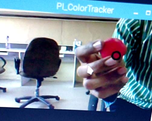
Once you are ready with the hardware and program it’s time to have some fun. Before we test our bot on ground, we should make sure everything is working fine. Connect your Pi to monitor and launch the processing code. You should see the video feed on a small window. Now, bring the ball inside the frame and click on the ball to teach the robot that it should track this particular colour. Now move the ball around the screen and you should notice the wheels rotating.
If everything is working as expected, release the bot on the ground and started playing with it. Make sure the room is evenly illuminated for best results. The complete working of the project is shown in the video below. Hope you understood the project and enjoyed building something similar. If you have any problems feel free to post them on the comment section below or help.
Complete Project Code
/*
Processing Raspberry Pi program for Ball following Robot
Project by: B.Aswnith Raj
Dated on: 18-11-2017
#This project would not have been possible without the help of Daniel Shiffman and Gottfried Haider
*/
import processing.io.*;
import gohai.glvideo.*;
GLCapture video;
color trackColor;
void setup() {
  size(320, 240, P2D);
  video = new GLCapture(this);
  video.start();

  trackColor = color(255, 0, 0);

  GPIO.pinMode(4, GPIO.OUTPUT);
  GPIO.pinMode(14, GPIO.OUTPUT);
  GPIO.pinMode(17, GPIO.OUTPUT);
  GPIO.pinMode(18, GPIO.OUTPUT);
}
void draw() {
   background(0);
  if (video.available()) {
    video.read();
  }

  video.loadPixels();
  image(video, 0, 0);

  float worldRecord = 500;
  int closestX = 0;
  int closestY = 0;

  // Begin loop to walk through every pixel
  for (int x = 0; x < video.width; x ++ ) {
    for (int y = 0; y < video.height; y ++ ) {
      int loc = x + y*video.width;
      // What is current color
      color currentColor = video.pixels[loc];
      float r1 = red(currentColor);
      float g1 = green(currentColor);
      float b1 = blue(currentColor);
      float r2 = red(trackColor);
      float g2 = green(trackColor);
      float b2 = blue(trackColor);
      // Using euclidean distance to compare colors
      float d = dist(r1, g1, b1, r2, g2, b2); // We are using the dist( ) function to compare the current color with the color we are tracking.
      // If current color is more similar to tracked color than
      // closest color, save current location and current difference
      if (d < worldRecord) {
        worldRecord = d;
        closestX = x;
        closestY = y;
      }
    }
  }

  if (worldRecord < 10) {
    // Draw a circle at the tracked pixel
    fill(trackColor);
    strokeWeight(4.0);
    stroke(0);
    ellipse(closestX, closestY, 16, 16);
    println(closestX,closestY);

    if (closestX<140)
    {
     GPIO.digitalWrite(4, GPIO.HIGH);
     GPIO.digitalWrite(14, GPIO.HIGH);
     GPIO.digitalWrite(17, GPIO.HIGH);
     GPIO.digitalWrite(18, GPIO.LOW);
     delay(10);
     GPIO.digitalWrite(4, GPIO.HIGH);
     GPIO.digitalWrite(14, GPIO.HIGH);
     GPIO.digitalWrite(17, GPIO.HIGH);
     GPIO.digitalWrite(18, GPIO.HIGH);

     println("Turn Right");
    }
    else if (closestX>200)
    {
     GPIO.digitalWrite(4, GPIO.HIGH);
     GPIO.digitalWrite(14, GPIO.LOW);
     GPIO.digitalWrite(17, GPIO.HIGH);
     GPIO.digitalWrite(18, GPIO.HIGH);
     delay(10);
     GPIO.digitalWrite(4, GPIO.HIGH);
     GPIO.digitalWrite(14, GPIO.HIGH);
     GPIO.digitalWrite(17, GPIO.HIGH);
     GPIO.digitalWrite(18, GPIO.HIGH);
     println("Turn Left");
    }
    else if (closestY<170)
    {
     GPIO.digitalWrite(4, GPIO.HIGH);
     GPIO.digitalWrite(14, GPIO.LOW);
     GPIO.digitalWrite(17, GPIO.HIGH);
     GPIO.digitalWrite(18, GPIO.LOW);
     delay(10);
     GPIO.digitalWrite(4, GPIO.HIGH);
     GPIO.digitalWrite(14, GPIO.HIGH);
     GPIO.digitalWrite(17, GPIO.HIGH);
     GPIO.digitalWrite(18, GPIO.HIGH);
     println("Go Frwd");
    }
    else
     {
     GPIO.digitalWrite(4, GPIO.HIGH);
     GPIO.digitalWrite(14, GPIO.HIGH);
     GPIO.digitalWrite(17, GPIO.HIGH);
     GPIO.digitalWrite(18, GPIO.HIGH);
     }
  }
  else
  {
     GPIO.digitalWrite(4, GPIO.HIGH);
     GPIO.digitalWrite(14, GPIO.HIGH);
     GPIO.digitalWrite(17, GPIO.HIGH);
     GPIO.digitalWrite(18, GPIO.HIGH);
  }
}
void mousePressed() {
  // Save color where the mouse is clicked in trackColor variable
  int loc = mouseX + mouseY*video.width;
  trackColor = video.pixels[loc];
}
Comments
even i facing this problem
I did not face any issue using this. Try with a USB webcam and let me know if that is working.
to solve this error
type" sudo modprobe bcm2835-v4l2" in rasp terminal
then run your processing code
This is a nice article . You did a very good job of explaining every part of the program. Much easier to follow then the machine learning presentation I went to the other day..
Do you think you can do a presentation on how to get a robot to learn how to follow you on a paved pathway? Even navigate walkways from one point to another point?
Yes I can. It should be easy. Will give it a try when I find time.
An error appears saying " duplicate libraries are used for I/O one of libraries must be removed "
Out of curiosity you should have installed the library twice just un-install any one library
Plz Slove my problem there is one error on
new GLCapture (this)
I am use raspberry pi camera
Error:no capture device found plz fast
Iam getting error in code .
Error : " Duplicate libraries are found "
You should have messed up while trying to install library. Do to the directry and remove the library and install again
iam getting error that sketch couldnt run. what is the problem ?
I have completed all of the steps but when I run it, the program says "No capture devices found" I have also tried a USB camera which has the same results.
This is a very frustrating problem with PI cameras!! Are you able to access the feed through some other application? The problem is coming because your PI cannot discover the CAM
after i run the program the cam is identifying the ball and executing the program but motors are not rotating
I think you have made some mistake in the circuit!! did you check your connections? Use the multimeter to check if that particular pin is going high
Plzz can you me help me find the solution to this ..........I m making this robot as my college project and I don't have a webcam to use as alternative
If we use usb camera, then do we need to change anything in code?
If that is the only camera attached to you computer. Then no, no changes are required.
hello B.Aswinth Raj,
I am working on a project of tower crane which is not really similar to your project but, I have wrote a code for positioning the hoist (trolley) along the crane jib in Arduino. and I need to use a camera which should be located underneath the hoist to look at the load while travelling to determine where the load is while travelling.
is possible to use a code that similar to your code which allows the camera to send a feedback to the Arduino which make the motors move to keep the load under the hoist during the travelling(without swing). furthermore, how to connect or interface my Arduino code for motor positioning with camera code?
I would be thankful for reply
Bilal
Hi sir
Thanks for your valuable effort for sharing such a great project with code.
I followed your instruction and successfully completed the project.
Problem faced:
i)Duplicate libraries found for IO
ii)Video capture couldn't found any capture device
Solution:
i)Only install the video capture library. Hardware IO is already their in processing lib.
II)For the second problem
in /etc/modules add- bcm2835_v4l2
then reboot
just type command ls /dev/*, it will show one entry as video0.This implies successful detection of camera module
Then the code will work perfectly both for pi-Cam and webcam.
Dear Harish sir,
Can you please tell me how to add bcm2835_v4l2 in /etc/modules?
and please tell me from where we can get this?
"RuntimeException: /sys/class/gpio/gpio4/direction: No such file or directory" i am getting this error does anyone having solution for this....thanks in advance.
"RuntimeException: /sys/class/gpio/gpio4/direction: No such file or directory" i am getting this error does anyone having solution for this....thanks in advance.
"RuntimeException: /sys/class/gpio/gpio4/direction: No such file or directory" i am getting this error does anyone having solution for this....thanks in advance.
after setting up all the things on the RPi ( installing all requires) and load the code (that I write in my laptop for counting people using Open CV for example), can I unplug the RPi from the computer and install it in a place where I planned to count people for example buildings? How it work that way without a computer? is that possible to load the counting code on the pi using the SD card and will work fine as intended? please leave me comment in my email
Yes it is possible, you can either use a display connected to the HDMI pin of pi or just remotely launch the pi script form a shell window
I run the program i have two errors
1) duplicate libraries
2) No capture device found
The first error is because you have installed two libraries in the same name. Go the library directory and delete the one you are not using.
The second error is because the program cannot find your webcam
I solved the "duplicate library "error and i run the sketch. but i got only a black screen window instead of video feed. when i click on the black feed. the code works fine and motor driving commands working well.
how to remove this black window problem
A black window? this means that your pi is not able to read the camera feed. Check the video it shows how the program should respond when launched
have you solved this problem because I am facing the same problem
have you solved this problem because I am facing the same problem
Thank dear...
When i run the code ,this error pops up :
java.lang.RuntimeException: Cannot link shader program:
ERROR:PREPROCESSOR-1 (vertex shader, line 1) Preprocessor syntax error : garbage at end of preprocessor directive
at processing.core.PGraphics.showException(PGraphics.java:8206)
at processing.opengl.PShader.validate(PShader.java:937)
at processing.opengl.PShader.init(PShader.java:902)
at processing.opengl.PShader.getAttributeLoc(PShader.java:595)
at processing.opengl.PShader.loadAttributes(PShader.java:1123)
at processing.opengl.PGraphicsOpenGL.getPolyShader(PGraphicsOpenGL.java:7081)
at processing.opengl.PGraphicsOpenGL.flushPolys(PGraphicsOpenGL.java:2378)
at processing.opengl.PGraphicsOpenGL.flush(PGraphicsOpenGL.java:2315)
at processing.opengl.PGraphicsOpenGL.endDraw(PGraphicsOpenGL.java:1480)
at processing.core.PApplet.handleDraw(PApplet.java:2444)
at processing.opengl.PSurfaceJOGL$DrawListener.display(PSurfaceJOGL.java:866)
at jogamp.opengl.GLDrawableHelper.displayImpl(GLDrawableHelper.java:692)
at jogamp.opengl.GLDrawableHelper.display(GLDrawableHelper.java:674)
at jogamp.opengl.GLAutoDrawableBase$2.run(GLAutoDrawableBase.java:443)
at jogamp.opengl.GLDrawableHelper.invokeGLImpl(GLDrawableHelper.java:1293)
at jogamp.opengl.GLDrawableHelper.invokeGL(GLDrawableHelper.java:1147)
at com.jogamp.newt.opengl.GLWindow.display(GLWindow.java:759)
at com.jogamp.opengl.util.AWTAnimatorImpl.display(AWTAnimatorImpl.java:81)
at com.jogamp.opengl.util.AnimatorBase.display(AnimatorBase.java:452)
at com.jogamp.opengl.util.FPSAnimator$MainTask.run(FPSAnimator.java:178)
at java.util.TimerThread.mainLoop(Timer.java:555)
at java.util.TimerThread.run(Timer.java:505)
can anyone help me solve this issue plz...
when i'm compiling the error was give to me as "camera not found" but i check my camera. it is working properly, Why is tht?????
how much will it cost ?All the parts i mean
Raspberry Pi is the costly part its around 3K INR. The rest should be less than 1.5K INR
the code is running without any errors but I am getting a black camera window. Does anybody know how to resolve it
type this command in raspberry pi terminal
sudo modprobe bcm2835-v4l2
then run your processing code... cheers
to solve this error (black window)
type this command in raspberry pi terminal
sudo modprobe bcm2835-v4l2
then run your processing code... cheers
type this command in raspberry pi terminal
sudo modprobe bcm2835-v4l2
then run your processing code... cheers
type this command in raspberry pi terminal
sudo modprobe bcm2835-v4l2
then run your processing code... cheers
Hi!
I wanted to personally thank you for putting the time and effort to write this tutorial, if I could get your contact information that would be great, my email is seifaeim@merrimack.edu if you could ever send me an email as soon as you get a chance to I would really appreciate it.
Basically, I am building a ball fetching robot and am using a lot of your guidance from this tutorial. My proposed robot will potentially recognize tennis balls on the court, move towards them and collect them from the ground into a container. I wanted to see if you have the code for the part that connects the process of recognizing the ball using image processing to the part that makes the wheels move. In summary, I would really appreciate it if you could share your completed code (of recognizing the tennis balls and sending a signal to the motors to start moving the wheels towards the target) for this project with me? I would really appreciate it! Thank you so much again.
Best,
Mana
Sir Why are you connecting mouse and keyboard with Pi?
"RuntimeException: /sys/class/gpio/gpio4/direction: No such file or directory" i am getting this error does anyone having solution for this....thanks in advance.
Looks strange, I think there is someproblm with using the GPIO4 pin. Try using some other pin for GPIO4.
The reason is Physical pin 7 ( gpio4) is also used as the default pin for the 1-wire interface that may have been what caused your problem, especially if 1-wire interface was enabled.
So if you want to use GPIO4 for I/O purpose you have to disable 1-wire interface under pi configuration. else you are free to use any other GPIO pin
The code runs perfectly but returns a black screen on camera window. Both in case of Pi Cam and also USB webcam. anyone knows how to fix it??
It is not showing any error even the camera light in my webcam is also running. That means it detects and turns on the camera. then why the camera screen remains black all the time? Please help me to solve this.
I am working on a similar project and trying to implement obstacle avoidance using ultrasonic sensor. Kindly help me with the code because I am facing difficulties in coding the same on processing IDE.
Hi!
I wanted to personally thank you for putting the time and effort to write this tutorial, if I could get your contact information that would be great, my email is Nishant.Katalkar12@gmail.com and my contact no is 8692086988 if you could ever send me an email as soon as you get a chance to I would really appreciate it.
I want to ask a few questions related with the connections as i am slightly confused as it is my first iot project. I need ur help . plz if u can .
Thank u
I want to when I power on raspberry pi it,s will be auto working .. but I unable to solve this problem. please help me. the color will be fixed no selected by mouse.
Hello Sir. I am getting this error.
String Index Out of range: -1
what could be the problem
Hello Aswinth Raj,
My name is Yousef I want to let you know that, I am working on a project very similar to yours, and I need your advise and maybe help on some the things. If you are open for help I would be very thankful.
Please let me know so we can work somthing out. You can contact me through joeabe90@gmail.com for further discussion.
Thank you in advance
Hello Aswinth Raj,
I am working on simliar project robot following red object using rasbarry pi and ultrasonic sensors. I tried to implement your project for the seek of learning but I faced some problem and I coudn't get it working. I want to ask you if you are open for help, and me and you can work somthing out definitely that will benefit both of us.
Please let me know if you can, My name is Zack Abe.
Thank you in advance

I did all the steps have been taken, but
Then click on run program does not run : error is "No capture devices found"
I use Raspberry Pi 3 and the camera OVA5647 (precisely your camera)
The camera was previously tested by the following tutorials
"Visitor Monitoring System with Raspberry Pi and Pi Camera"
My camera is working
Help me solve my problem