
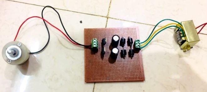
The objective of this project is to convert 220V AC supply in to +12V and -12v DC supply, that is why it is named Dual Power Supply as we get positive and negative 12v power supply at the same time.
This can be achieved in simple three steps:
- Firstly, 220V AC is converted into 12V AC by using simple step-down (220V/12V) transformer.
- Secondly, output of this transformer is given to the rectifier circuit, which will convert the ac supply into dc supply. The output of the rectifier circuit that is DC contains the ripples in the output voltage. To filter out these ripples, capacitor of 2200 uf, 25V is used.
- Lastly, the output of the capacitor that is pure DC is given to voltage regulator IC 7812 and IC7912 which will regulate the output voltage at 12V and -12V DC, despite the change in input voltage.
Required Components:
- Centre tapped transformer (220V/12V)
- Power Diodes (6A) – 4No.
- Capacitor (2200μF, 25V) – 2No.
- Voltage regulator (IC 7812 & 7912)
- Toggle switch
- DC load (DC motor)
Circuit Diagram:

Constructing Dual Power Supply Circuit:
Step-I: Converting 220v AC into 12v AC using Step Down Transformer
The primary terminals of the centre tapped transformer is connected with household supply (220V ac, 50Hz) and output is taken from secondary terminals of the transformer. The centre tapped describes the voltage output of a center tapped transformer. For example: A 24V centre tapped transformer will measure 24V ac across the outer two taps (winding as a whole), and 12V ac from each outer tap to the center-tap (half winding). These two 12V ac supplies are 180 degrees out of phase with each other, thus making it easy to derive positive and negative 12 volt dc power supplies from them. The advantage of using a centre tapped transformer is we can get the both +12V and -12V dc supply using only one transformer.

INPUT: 220V ac, 50 Hz
OUTPUT: Between outer terminal and middle terminal: 12V ac, 50 Hz
Between two outer terminals: 24V ac. 50 Hz
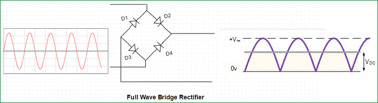
Step – II: Converting 12v AC into 12v DC using Full Bridge Rectifier
The outer two terminals of the centre tapped transformer are connected to the bridge rectifier circuit. Rectifier circuit is a converter, which converts ac supply in to dc supply. It is generally made up of diode switches as shown in Circuit Diagram.
To convert ac into dc, we can make two types of rectifiers, one is half bridge rectifier and second is full bridge rectifier. In half bridge rectifier, output voltage is half of the input voltage. For example, if input voltage is 24V, then output dc voltage is 12V and number of diode used in this type of rectifier is 2. In full bridge rectifier, number of diodes is 4 and it is connected as shown in figure and output voltage is same as the input voltage.
Here, full bridge rectifier is used. So, number of diodes are 4 and input voltage (24V ac) and output voltage is also 24V dc with ripples in it.
For, full bridge rectifier output voltage,
VDC = 2Vm / Π where, Vm=peak value of ac supply voltage and Π is Pi
The waveform of input and output voltage of full bridge rectifier is as shown below.
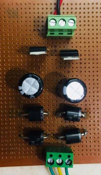
In this Dual Power Supply Circuit, Diode bridge rectifier is made up of 6A four power diodes. Rating of this diode is 6A and 400V. It is not necessary to use this much of high current capacity diode but because of safety and flexibility purpose, high current capacity diode is used. Generally, because of surges in current, it is possible to damage the diode, if we used low ampere rating diode.
The output of rectifier is not pure dc, but it contains ripples in it.
INPUT: 12V ac
OUTPUT: 24V peak (with ripples)
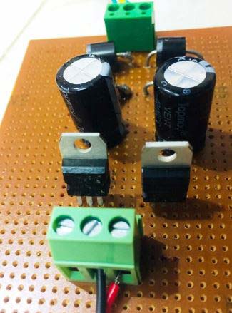
Step-III: Filter the Ripples from the output:
Now, 24V dc output which contains peak to peak ripples can’t be connected directly to the load. So, to remove ripples from the supply, filter capacitors are used. Now, two filter capacitor of rating 2200uF and 25 V are used as shown in circuit diagram. The connection of both capacitors are such that the common terminal of the capacitors is connected directly to the centre terminal of the centre tapped transformer. Now, this capacitor will get charged upto 12V dc as both are connected with the common terminal of a transformer. Furthermore, the capacitors will remove the ripples from the dc supply and give a pure dc output. But, the output of both the capacitors are not regulated. So, to make the supply regulated, output of the capacitors are given to the voltage regulator ICs which is explained in next step.
INPUT: 12V dc (with ripples, not pure)
OUTPUT: Voltage across capacitor C1 =12V dc (pure dc, but not regulated)
Voltage across capacitor C2 =12V dc (pure dc, but not regulated)
Step-IV: Regulate the 12v DC Power Supply
The next important thing is to regulate the output voltage of the capacitors which will otherwise be varying as per the input voltage change. For that depending upon the output voltage requirement, regulator ICs are used. If we need the output voltage +12V then IC 7812 is used. If required output voltage is +5V, then 7805 IC is used. Last two digits of the IC gives output voltage rating. Third last digit shows voltage is positive or negative. For positive voltage (8) and for negative voltage (9) number is used. So IC7812 is used for +12v regulation and IC7912 is used for -12v voltage regulation.
Now connection of two ICs are done as shown in circuit diagram. The ground terminal of both ICs are connected with the centre tap terminal of the transformer in order to create a reference. Now, the output voltages are measured between the output terminal and ground terminal for both ICs.
INPUT: 12V dc (pure dc but not regulated)
OUTPUT: +12V dc between output terminal of 7812 and Ground (pure dc and regulated)
-12V dc between output terminal of 7912 and Ground (pure dc and regulated)
Applications of Dual Power Supply Circuit:
- Operational amplifiers need two power sources (usually one +ve source and one -ve source) because the op-amp must operate in both polarities of the incoming signal. Without the negative source, the op-amp won't swing into action during the negative cycle of the signal. So that signal portion's output will "clipped", that is, remain at ground itself; which is obviously not recommended.
- If DC motors are used as a load, then for +12V it will rotate in clockwise direction and for -12V it will rotate in opposite direction. For example, motors which are used in toys (car, bus etc), will move forward in case of +12V and it will move reverse in case of -12V. We have shown the motor rotation in both the directions, using this Dual Power Supply circuit, in the Video below.
Check our other Power Supply Circuit:
Comments
The supply voltage is 220V ADC which is stepped down to 12V AC transformer. So this AC voltage voltage has to be rectified to DC since we need Dual Dc voltages.
What will the circuit for for +12 v DC / -12V DC and + 5 v DC
Thanks ,
Amit
Sir plz help how to make -5 to +5 power supply plz sir i want circuit diagram of -5 to +5 power supply with label of component value , thank you sir ,must reply sir plz its urgent
In your diagram you make use of 220v-24v center tapped transformer which later supplied each 12volts voltage regulators with exactly 12volts, but from one of your initial explanations you said to supply a voltage regulator IC, the input voltage should be at least 2volts greater than the ouput voltage. But that is not applicable here. Please explain.
Yeah, I think there has been a mistake, but 7812 can regulate 12V even if we provide only 12V as input
How to increase output current.
What are the alternatives to the resistors/capacitors and the rectifier ICs if we need 3A output?

WHY DID THE SWITCHING SUPPLY USED TO RECTIFICATION?
BUT THIS CIRCUIT IS VERY SIMPLE & HELPFUL.