

In this tutorial we are going to interface a DC motor to Arduino UNO and control it's speed using PWM (Pulse Width Modulation) concept. This feature is enabled in UNO to get variable voltage over constant voltage. The method of PWM is explained here; consider a simple circuit as shown in figure. This tutorial uses the L293D IC, we have also built a DC motor speed controller using MOSFET. You can also check that out if you are intrested.
If the button is pressed if the figure, then the motor will start rotating and it will be in motion until the button is pressed. This pressing is continuous and is represented in the first wave of figure. If, for a case, consider button is pressed for 8ms and opened for 2ms over a cycle of 10ms, during this case the motor will not experience the complete 9V battery voltage as the button is pressed only for 8ms, so the RMS terminal voltage across the motor will be around 7V. Due to this reduced RMS voltage the motor will rotate but at a reduced speed. Now the average turn on over a period of 10ms = Turn ON time/ (Turn ON time + Turn OFF time), this is called duty cycle and is of 80% (8/ (8+2)).
In second and third cases the button is pressed even lesser time compared to first case. Because of this, the RMS terminal voltage at the motor terminals gets even decreased further. Due to this reduced voltage the motor speed even decreases further. This decrease in speed with duty cycle continuous to happen until a point, where the motor terminal voltage will not be sufficient to turn the motor.
So by this we can conclude the PWM can be used to vary the motor speed.
Before going further we need to discuss the H-BRIDGE. Now this circuit has mainly two functions, first is to drive a DC motor from low power control signals and the other is to change the direction of rotation of DC motor.
Figure 1
Figure 2
We all know that for a DC motor, to change the direction of rotation, we need to change the polarities of supply voltage of motor. So to change the polarities we use H-bridge. Now in above figure1 we have fours switches. As shown in figure2, for the motor to rotate A1 and A2 are closed. Because of this, current flows through the motor from right to left, as shown in 2nd part of figure3. For now consider the motor rotates clockwise direction. Now if the switches A1 and A2 are opened, B1 and B2 are closed. The current through the motor flows from left to right as shown in 1st part of figure3. This direction of current flow is opposite to the first one and so we see an opposite potential at motor terminal to the first one, so the motor rotates anti clock wise. This is how an H-BRIDGE works. However low power motors can be driven by a H-BRIDGE IC L293D.
L293D is an H-BRIDGE IC designed for driving low power DC motors and is shown in figure. This IC consists two h-bridges and so it can drive two DC motors. So this IC can be used to drive robot's motors from the signals of microcontroller.
Now as discussed before this IC has ability to change the direction of rotation of DC motor. This is achieved by controlling the voltage levels at INPUT1 and INPUT2.
Enable Pin | Input Pin 1 | Input Pin 2 | Motor Direction |
High | Low | High | Turn Right |
High | High | Low | Turn Left |
High | Low | Low | Stop |
High | High | High | Stop |
So as shown in above figure, for clockwise rotation 2A should be high and 1A should be low. Similarly for anti clockwise 1A should be high and 2A should be low.
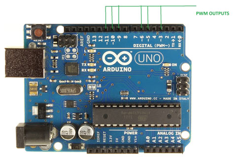
As shown in the figure, Arduino UNO has 6PWM channels, so we can get PWM (variable voltage) at any of these six pins. In this tutorial we are going to use PIN3 as PWM output.
Hardware: ARDUINO UNO, power supply (5v), 100uF capacitor ,LED, buttons (two pieces), 10KΩ resistor (two pieces).
Software: arduino IDE (Arduino nightly).
Circuit Diagram

The circuit is connected in breadboard as per the circuit diagram shown above. However one must pay attention during connecting the LED terminals. Although the buttons show bouncing effect in this case it does not cause considerable errors so we need not worry this time.
The PWM from UNO is easy, on normal occasions setting up a ATMEGA controller for PWM signal is not easy, we have to define many registers and settings for a accurate signal, however in ARDUINO we don’t have to deal with all those things.
By default all the header files and registers are predefined by ARDUINO IDE, we simply need to call them and that’s it we will have a PWM output at appropriate pin.
Now for getting a PWM output at a appropriate pin, we need to work on three things,
|
First we need to choose the PWM output pin from six pins, after that we need to set that pin as output.
Next we need to enable the PWM feature of UNO by calling the function “analogWrite(pin, value)” . In here ‘pin’ represent the pin number where we need PWM output we are putting it as ‘3’. So at PIN3 we are getting PWM output.
Value is the turn ON duty cycle, between 0 (always off) and 255 (always on). We are going to increment and decrement this number by button press.
The UNO has a maximum resolution of “8”, one cannot go further hence the values from 0-255. However one can decrease the resolution of PWM by using command “analogWriteResolution()”, by entering a value from 4-8 in the brackets, we can change its value from four bit PWM to eight bit PWM.
The switch is to change the direction of rotation for DC motor.
Complete Project Code
volatile int i=0;//initializing a integer for incrementing and decrementing duty ratio.
void setup()
{
                pinMode(3, OUTPUT);   // sets the pin3 as output
                pinMode(0, INPUT);// sets the pin0 as output
                pinMode(1, INPUT);// sets the pin1 as output
}

void loop()
{
                analogWrite(3, i);  // analogWrite values from 0 to 255
                if (digitalRead(0)==LOW)
                {
                                if (i<255)
                                {
                                                i++;//if pin0 is pressed and the duty ratio value is less than 255
                                                delay(30);
                                }
                }
                if (digitalRead(1)==LOW)
                {
                                if (i>0)
                                {
                                                i--;// if pin1 is pressed and the duty ratio value is greater than 0
                                                delay(30);
                                }
                }
}
Comments
fritzing circuit diagram can not understand plz upload actual circuit schematic circuit diagram
controlling Dc motor speed and direction base on feedback analog signal ,please help me how can write arduino code.
plz upload detailed ckt diagram
You do not show where the 100 microF Cap is connected?
Your code comments states Pins 0 and 1 as output
What tyoe of motor is that? I mean is it <5v or is it >5v?

What is the maximum voltage the L293D chip can apply to a motor if the input for the driver voltage is 5V ? The chip would have an internal voltage drop correct ? So that the maximum effective output voltage driving a motor ( at full speed )would be less that the input provided for the motor correct ? I don't see this fact included in your nice tutorial here. I need this info.