

Stepper motors are increasingly taking its position in the world of the electronics. Starting from a normal Surveillance camera to a complicated CNC machines/Robot these stepper motors are used everywhere as actuators since they provide accurate controlling. A Stepper Motor is a brushless, synchronous motor which completes a full rotation into a number of steps. In this Arduino stepper motor tutorial we will learn about the most commonly available stepper motor 28-BYJ48 and how to interface it with Arduino using ULN2003 stepper motor module.
Stepper Motors:
Let us take a look at this 28-BYJ48 Stepper motor.
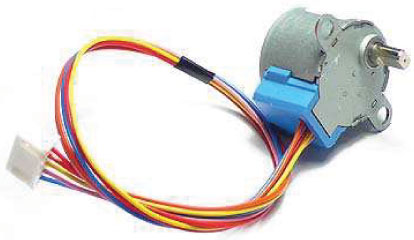
Okay, so unlike a normal DC motor this one has five wires of all fancy colors coming out of it and why is it so? To understand this we should first know how a stepper works and what its specialty is. First of all steppers motors do not rotate, they step and so they also known as step motors. Meaning, they will move only one step at a time. These motors have a sequence of coils present in them and these coils have to be energized in a particular fashion to make the motor rotate. When each coil is being energized the motor takes a step and a sequence of energization will make the motor take continuous steps, thus making it to rotate. Let us take a look at the coils present inside the motor to know exactly know from where these wires come from.
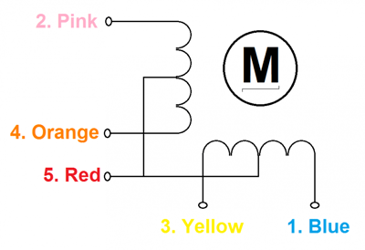
As you can see the motor has Unipolar 5-lead coil arrangement. There are four coils which have to be energized in a particular sequence. The Red wires will be supplied with +5V and the remaining four wires will be pulled to ground for triggering the respective coil. We use a microcontroller like Arduino energize these coils in a particular sequence and make the motor perform the required number of steps.
So now, why is this motor called the 28-BYJ48? Seriously!!! I don’t know. There is no technical reason for this motor for being named so; maybe we should dive much deeper into it. Let us look at some of the important technical data obtained from the datasheet of this motor in the picture below.

That is a head full of information, but we need to look at few important ones to know what type of stepper we are using so that we can program it efficiently. First we know that it is a 5V Stepper motor since we energize the Red wire with 5V. Then, we also know that it is a four phase stepper motor since it had four coils in it. Now, the gear ratio is given to be 1:64. This means the shaft that you see outside will make one complete rotation only if the motor inside rotates for 64 times. This is because of the gears that are connected between the motor and output shaft, these gears help in increasing the torque.
Another important data to notice is the Stride Angle: 5.625°/64. This means that the motor when operates in 8-step sequence will move 5.625 degree for each step and it will take 64 steps (5.625*64=360) to complete one full rotation. You can learn more about working of stepper motors with ARM LPC2148, ATMega16 Microcontroller, MSP430.
Calculating the Steps per Revolution for Stepper Motor:
It is important to know how to calculate the steps per Revolution for your stepper motor because only then you can program it effectively.
In Arduino we will be operating the motor in 4-step sequence so the stride angle will be 11.25° since it is 5.625°(given in datasheet) for 8 step sequence it will be 11.25° (5.625*2=11.25).
Steps per revolution = 360/step angle
Here, 360/11.25 = 32 steps per revolution.
Why so we need Driver modules for Stepper motors?
Most stepper motors will operate only with the help of a driver module. This is because the controller module (In our case Arduino) will not be able to provide enough current from its I/O pins for the motor to operate. So we will use an external module like ULN2003 module as stepper motor driver. There are a many types of driver module and the rating of one will change based on the type of motor used. The primary principle for all driver modules will be to source/sink enough current for the motor to operate.
Arduino Stepper Motor Position Control Circuit Diagram and Explanation:

The circuit Diagram for the arduino stepper motor control project is shown above. We have used the 28BYJ-48 Stepper motor and the ULN2003 Driver module. To energise the four coils of the stepper motor we are using the digital pins 8,9,10 and 11. The driver module is powered by the 5V pin of the Arduino Board.
But, power the driver with External Power supply when you are connecting some load to the steppe motor. Since I am just using the motor for demonstration purpose I have used the +5V rail of the Arduino Board. Also remember to connect the Ground of the Arduino with the ground of the Diver module.
Code for Arduino Board:
Before we start programming with our Arduino, let us understand what should actually happen inside the program. As said earlier we will be using 4-step sequence method so we will have four steps to perform for making one complete rotation.
|
Step |
Pin Energized |
Coils Energized |
|
Step 1 |
8 and 9 |
A and B |
|
Step 2 |
9 and 10 |
B and C |
|
Step 3 |
10 and 11 |
C and D |
|
Step 4 |
11 and 8 |
D and A |
The Driver module will have four LED using which we can check which coil is being energised at any given time. The video which shows the sequence of energization can be found at the end of this tutorial.
In this tutorial we are going to write the arduino stepper motor code and for that we will program the Arduino in such a way that we can enter the number of steps to be taken by the stepper motor through the serial monitor of the Arduino. The complete program can be found at the end of the tutorial few important lines are explained below.
The number of steps per revolution for our stepper motor was calculated to be 32; hence we enter that as shown in the line below
#define STEPS 32
Next you have to create instances in which we specify the pins to which we have connected the Stepper motor.
Stepper stepper (STEPS, 8, 10, 9, 11);
Note: The pins number are disordered as 8,10,9,11 on purpose. You have to follow the same pattern even if you change the pins to which your motor is connected.
Since we are using the Arduino stepper library, we can set the speed of the motor using the below line. The speed can range between 0 to 200 for 28-BYJ48 stepper motors.
stepper.setSpeed(200);
Now, to make the motor move one step we can use the following line.
stepper.step(val);
The number of steps to be moved will be provided by the variable “val”. Since we have 32 steps and 64 as the gear ratio we need to move 2048 (32*64=2048), to make one complete rotation.
The value of the variable “val” can be entered by the user using the serial monitor.

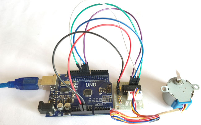
Working of Stepper Motor with Arduino:
Once the connection is made the hardware should look something like this in the picture below.
Now, upload the below program in your Arduino UNO and open the serial monitor. As discussed earlier we will have to make 2048 steps to make one complete rotation, so when we enter 2048 the motor will make one complete rotation in clockwise direction by making 2048 steps. To rotate in anti-clockwise just enter the number with “–“negative sign. So, entering -1024 will make the motor to rotate half the way in anti-clock wise direction. You can enter any desired values, like entering 1will make the motor to take only one step.
Hope you understood the project and enjoyed building it. The complete working of the project is shown in the video below. If you have any doubts post them on the comment section below our on our forums.
Complete Project Code
// Arduino stepper motor control code
#include <Stepper.h> // Include the header file
// change this to the number of steps on your motor

#define STEPS 32
// create an instance of the stepper class using the steps and pins

Stepper stepper(STEPS, 8, 10, 9, 11);

int val = 0;
void setup() {

  Serial.begin(9600);

  stepper.setSpeed(200);

}
void loop() {
  if (Serial.available()>0)

  {

    val = Serial.parseInt();

    stepper.step(val);

    Serial.println(val); //for debugging

  }


}
Comments
seems good (Y) and simple concept explained well.
The circuit diagram is incorrect. I had it wired how you have it in the diagram and ran the code and it does nothing. I then noticed the way it is wired in the actual real pictures is also different from the diagram. I then moved the wires around to follow the one in the real pictures of the circuit and it worked. The correct wiring should be:
Blue - Pin 8
Pink/Purple - Pin 9
Yellow - Pin 10
Orange - Pin 11
Thanks for pointing it out Michael, and sorry for the mistake.
Hi,
I'm confused now, the sequence you list is not the same as either the picture or diagram, so I'm struggling to decide which one I need to follow. Is there any chance you could please list the shield's IN pin number to the Arduino pin number (i.e. Shield IN1 to Arduino Pin 8 or whatever pin it should be)?
Many Thnaks
Hey, thanks a lot! This helped me to understand the working of the stepper as well as the coding for the same.
DO you need to download the stepper.h file my code wont compile.
my stepper motor not working anti click wise.
What is the reason?
The stepper motor itself seems to get incredibly hot while idle (not moving) is there a way to cut the power off to it when it's not in use?
Thanks for sharing
Everything work fine, but the questions is what about other variables? I think about setSpeed, moveTo, setAcceleration, setMaxSpeed or clockwise. For me is more difficult because, I can send only one parameter(one of them)
Is this the maximum speed as seen in the video for this motor?
It looks like the speed can range between 0 to 1000 for 28-BYJ48 stepper motors.
i copied the code and tried to run it on my arduiono IDE but it showed me the following error:
class hardware serial has no member named parseint
i am using the code to run a stepper motor for my final year project at college. your assistance will be greatly appreciated. kind regards

nice article about Interfacing Stepper Motor with Arduino Uno
Thanks for sharing