

This is our sixth tutorial in our PIC Tutorial Series, in this tutorial we learn Interfacing of 16x2 LCD with PIC Microcontroller. In our previous tutorials we have learnt the basics of PIC using some LED blinking Programs and have also learnt How to use Timers in PIC Microcontroller. You can check here all the tutorials on Learning PIC Microcontrollers using MPLABX and XC8 compiler.
This tutorial will be an interesting one because we will learn How to Interface 16×2 LCD with PIC16F877A, check the detailed Video at the end this tutorial. Gone are the old days where we used LEDs for user indications. Let us see how we can make our projects look more cool and useful by using LCD displays. Also check our previous articles on Interfacing LCD with 8051, with Arduino, with Raspberry Pi, with AVR.
Functions for Interfacing LCD with PIC Microcontroller:
To make things easier we have made a small library that could make things easy while using this LCD with our PIC16F877A. The header file "MyLCD.h" is given here for download, which contains all the necessary function to drive the LCD using PIC MCU. Library code is well explained by comment lines but if you still have doubts reach us through the comment section. Also check this article for Basic LCD working and its Pinouts.
Note: It is always recommended to know what is actually happening inside your header file because it will help you in debugging or while changing the MCU.
Now, there are two ways to add this code into your program. You can either copy all the above lines of code in MyLCD.h and paste them before the void main(). Or you can download the header file using the link and add them to the header file of your project (#include " MyLCD.h ";). This can be done by right clicking on the header file and selecting Add existing Item and browsing to this header file.
Here I have copied and pasted the header file code into my main C file. So if you are using our code, then you don’t need to download and add the header file into your program, just use the complete Code given at the end of this Tutorial. Also note that this library will only support PIC16F series PIC Microcontroller.
Here I am explaining each function inside our header file below:
void Lcd_Start(): This function should be the first function that has to be called to start working with our LCD. We should call this function only once to avoid lag in the program.
void Lcd_Start()
{
  Lcd_SetBit(0x00);
  for(int i=1065244; i<=0; i--)  NOP();
  Lcd_Cmd(0x03);
    __delay_ms(5);
  Lcd_Cmd(0x03);
    __delay_ms(11);
  Lcd_Cmd(0x03);
  Lcd_Cmd(0x02); //02H is used for Return home -> Clears the RAM and initializes the LCD
  Lcd_Cmd(0x02); //02H is used for Return home -> Clears the RAM and initializes the LCD
  Lcd_Cmd(0x08); //Select Row 1
  Lcd_Cmd(0x00); //Clear Row 1 Display
  Lcd_Cmd(0x0C); //Select Row 2
  Lcd_Cmd(0x00); //Clear Row 2 Display
  Lcd_Cmd(0x06);
}
Lcd_Clear(): This function clears the LCD screen and can be used inside loops to clear the appearance of previous data.
Lcd_Clear()
{
    Lcd_Cmd(0); //Clear the LCD
    Lcd_Cmd(1); //Move the cursor to first position
}
void Lcd_Set_Cursor(x pos, y pos): Once started, our LCD is ready to take commands, we can instruct the LCD to set its cursor in you preferred location by using this function. Suppose if, we need out cursor at 5th character of 1st row. Then the function will be void Lcd_Set_Cursor(1, 5)
void Lcd_Set_Cursor(char a, char b)
{
    char temp,z,y;
    if(a== 1)
    {
      temp = 0x80 + b - 1; //80H is used to move the cursor
        z = temp>>4; //Lower 8-bits
        y = temp & 0x0F; //Upper 8-bits
        Lcd_Cmd(z); //Set Row
        Lcd_Cmd(y); //Set Column
    }
    else if(a== 2)
    {
        temp = 0xC0 + b - 1;
        z = temp>>4; //Lower 8-bits
        y = temp & 0x0F; //Upper 8-bits
        Lcd_Cmd(z); //Set Row
        Lcd_Cmd(y); //Set Column
    }
}
void Lcd_Print_Char(char data) : Once the cursor is set we can write a character to its position by simple calling this function.
void Lcd_Print_Char(char data)  //Send 8-bits through 4-bit mode
{
   char Lower_Nibble,Upper_Nibble;
   Lower_Nibble = data&0x0F;
   Upper_Nibble = data&0xF0;
   RS = 1;             // => RS = 1
   Lcd_SetBit(Upper_Nibble>>4);             //Send upper half by shifting by 4
   EN = 1;
   for(int i=2130483; i<=0; i--)  NOP();
   EN = 0;
   Lcd_SetBit(Lower_Nibble); //Send Lower half
   EN = 1;
   for(int i=2130483; i<=0; i--)  NOP();
   EN = 0;
}
void Lcd_Print_String(char *a): If a group of characters is to be displayed, then the string function can be used.
void Lcd_Print_String(char *a)
{
    int i;
    for(i=0;a[i]!='\0';i++)
       Lcd_Print_Char(a[i]);  //Split the string using pointers and call the Char function
}
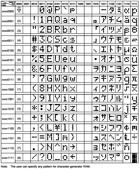
Each time the Lcd_Print_Char(char data) is called, its respective character values is sent to the data-lines of the LCD. These characters reach the HD44780U in form of bits. Now this IC relates the bits to the character to be displayed by using its ROM memory as shown the below table. You can find bits for all the characters in the datasheet of HD44780U LCD Controller.
Now, since we are satisfied with our header file let’s build the circuit and test the program. Also check complete header file given in the link given above.
Circuit Diagram and Testing:
Below is the circuit diagram for Interfacing 16x2 LCD with PIC Microcontroller.

I have not shown the Power supply or ICSP connection in the above circuit, since we are using the same board which we have used in previous tutorial, check here.
One important thing to notice in the program is the pin definitions of LCD:
#define RS RD2
#define EN RD3
#define D4 RD4
#define D5 RD5
#define D6 RD6
#define D7 RD7
These pin definitions can be changed according to the programmers hardware setup. Remember to change the respected port configuration in the main function if you change here.
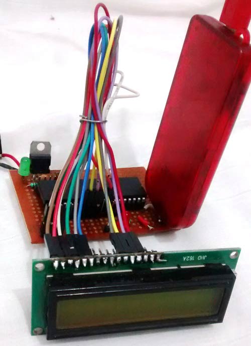
The hardware for this project is very simple. We are going to reuse the same PIC module that we used last time and connect the LCD module to our PIC using jumper wires.
The connection can be understood by the following table:
|
LCD Pin No. |
LCD Pin Name |
MCU Pin Name |
MCU Pin No. |
|
1 |
Ground |
Ground |
12 |
|
2 |
VCC |
+5V |
11 |
|
3 |
VEE |
Ground |
12 |
|
4 |
Register Select |
RD2 |
21 |
|
5 |
Read/Write |
Ground |
12 |
|
6 |
Enable |
RD3 |
22 |
|
7 |
Data Bit 0 |
NC |
- |
|
8 |
Data Bit 1 |
NC |
- |
|
9 |
Data Bit 2 |
NC |
- |
|
10 |
Data Bit 3 |
NC |
- |
|
11 |
Data Bit 4 |
RD4 |
27 |
|
12 |
Data Bit 5 |
RD5 |
28 |
|
13 |
Data Bit 6 |
RD6 |
29 |
|
14 |
Data Bit 7 |
RD7 |
30 |
|
15 |
LED Positive |
+5V |
11 |
|
16 |
LED Negative |
Ground |
12 |
Now let us simply make the connections, dump the code to our MCU and verify the output.
If you have any trouble or doubts, please use the comment section. Also check the Demo Video given below.
Complete Project Code
#define _XTAL_FREQ 20000000
#define RS RD2
#define EN RD3
#define D4 RD4
#define D5 RD5
#define D6 RD6
#define D7 RD7
#include <xc.h>
#pragma config FOSC = HS // Oscillator Selection bits (HS oscillator)
#pragma config WDTE = OFF // Watchdog Timer Enable bit (WDT disabled)
#pragma config PWRTE = ON // Power-up Timer Enable bit (PWRT enabled)
#pragma config BOREN = ON // Brown-out Reset Enable bit (BOR enabled)
#pragma config LVP = OFF // Low-Voltage (Single-Supply) In-Circuit Serial Programming Enable bit (RB3 is digital I/O, HV on MCLR must be used for programming)
#pragma config CPD = OFF // Data EEPROM Memory Code Protection bit (Data EEPROM code protection off)
#pragma config WRT = OFF // Flash Program Memory Write Enable bits (Write protection off; all program memory may be written to by EECON control)
#pragma config CP = OFF // Flash Program Memory Code Protection bit (Code protection off)
//LCD Functions Developed by Circuit Digest.
void Lcd_SetBit(char data_bit) //Based on the Hex value Set the Bits of the Data Lines
{
if(data_bit& 1)
D4 = 1;
else
D4 = 0;
if(data_bit& 2)
D5 = 1;
else
D5 = 0;
if(data_bit& 4)
D6 = 1;
else
D6 = 0;
if(data_bit& 8)
D7 = 1;
else
D7 = 0;
}
void Lcd_Cmd(char a)
{
RS = 0;
Lcd_SetBit(a); //Incoming Hex value
EN = 1;
__delay_ms(4);
EN = 0;
}
Lcd_Clear()
{
Lcd_Cmd(0); //Clear the LCD
Lcd_Cmd(1); //Move the curser to first position
}
void Lcd_Set_Cursor(char a, char b)
{
char temp,z,y;
if(a== 1)
{
temp = 0x80 + b - 1; //80H is used to move the curser
z = temp>>4; //Lower 8-bits
y = temp & 0x0F; //Upper 8-bits
Lcd_Cmd(z); //Set Row
Lcd_Cmd(y); //Set Column
}
else if(a== 2)
{
temp = 0xC0 + b - 1;
z = temp>>4; //Lower 8-bits
y = temp & 0x0F; //Upper 8-bits
Lcd_Cmd(z); //Set Row
Lcd_Cmd(y); //Set Column
}
}
void Lcd_Start()
{
Lcd_SetBit(0x00);
for(int i=1065244; i<=0; i--) NOP();
Lcd_Cmd(0x03);
__delay_ms(5);
Lcd_Cmd(0x03);
__delay_ms(11);
Lcd_Cmd(0x03);
Lcd_Cmd(0x02); //02H is used for Return home -> Clears the RAM and initializes the LCD
Lcd_Cmd(0x02); //02H is used for Return home -> Clears the RAM and initializes the LCD
Lcd_Cmd(0x08); //Select Row 1
Lcd_Cmd(0x00); //Clear Row 1 Display
Lcd_Cmd(0x0C); //Select Row 2
Lcd_Cmd(0x00); //Clear Row 2 Display
Lcd_Cmd(0x06);
}
void Lcd_Print_Char(char data) //Send 8-bits through 4-bit mode
{
char Lower_Nibble,Upper_Nibble;
Lower_Nibble = data&0x0F;
Upper_Nibble = data&0xF0;
RS = 1; // => RS = 1
Lcd_SetBit(Upper_Nibble>>4); //Send upper half by shifting by 4
EN = 1;
for(int i=2130483; i<=0; i--) NOP();
EN = 0;
Lcd_SetBit(Lower_Nibble); //Send Lower half
EN = 1;
for(int i=2130483; i<=0; i--) NOP();
EN = 0;
}
void Lcd_Print_String(char *a)
{
int i;
for(i=0;a[i]!='\0';i++)
Lcd_Print_Char(a[i]); //Split the string using pointers and call the Char function
}
int main()
{
unsigned int a;
TRISD = 0x00;
Lcd_Start();
while(1)
{
Lcd_Clear();
Lcd_Set_Cursor(1,1);
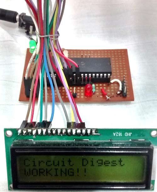
Lcd_Print_String("Circuit Digest");
Lcd_Set_Cursor(2,1);
Lcd_Print_String("WORKING!!");
__delay_ms(2000);
}
return 0;
}
Comments
No not suitable for 4x20 LCD
Sorry ANG!!
This header file will support only 16x2 LCD. But, if you want to use an 4x20 you have to come up with your own library by reading the datasheet of that particular LCD.
Can you tell me what kind of output you are getting!! may be i can guide you in the right path !!
Thanks!!
PIC16F877A with TC74 temperature sensor
Hi,
First of all, thank you for this awesome explanation. I'm actually working on Interfacing the PIC16F877A with a TC74 temperature sensor, can you guide me through please.
Thanks!!
You have to know I2C to interface TC74 with PIC
Hi MOMO,
Thank you for your words.
Interfacing TC74 with PIC requires you to know I2C In hand. I will make a tutorial to explain how to use I2C with PIC soon. I will also consider making a tutorial interface RC74 with PIC. If you have any other sensors in mind which you use frequently and would like to have a tutorial for that, list them below it will be of great use to me!!!
Thank you!!
I'm very pleased to discover
I'm very pleased to discover your site, and I commend the great work you are doing.
Thanks you very much for The
Thanks you very much for The tutorial. This is one of the best one I have ever seen.
hi. I tried this code on the
hi. I tried this code on the PIC16F690 but it doesn't work. I changed to PortC since the 16F690 doesn't have PortD but it still doesn't work. please help
Try out with simulation
Try out with simulation before proceeding with actual hardware. More over I cannot help you without looking at your codes
Hi, can you also provide the
Hi, can you also provide the explanation for the main part. I dont understand what are you doing at that part. Thank you.
use program with PIC16f1933
Hello,
I am trying to print to a 16x2 LCD screen with my PIC16F1933 using the code above. The programs compiles and gives no errors, but nothing is printed on the sreen. Except in the header file it gives a yellow triangle with the comment: "implicit signed to unsignedconversion"
Does someone know what the problem could be?
Thank you in advance
The problem is not with your
The problem is not with your program. Check your connection mainlhy the contrast pins
"Lcd_Cmd" is a function, to
"Lcd_Cmd" is a function, to know what it does you can look into the function definition of void Lcd_Cmd.
Simply put, it reads the HEX value as input parameters and sets the LCD register bits accordingly
suggestion to replace NOPs with more readable delays
You can use `__delay_ms(4)` instead of `for(int i=2130483; i<=0; i--) NOP()` and `__delay_ms(2)` instead of `for(int i=1065244; i<=0; i--) NOP()`
Yes you can, but its not
Yes you can, but its not advisable since the you wont have control on whats happening during the delay
Hi, thanks for the code you
Hi, thanks for the code you have given.
However, I can't seem to display anything on the 16x2 lcd module. The lcd is not broken and microcontroller seems to work perfectly fine, although what I used is the pic16f1937. Any thoughts on how will I make it work?
I also copied the exact same
I also copied the exact same code provided in your site.
IS you connection correct? I
IS you connection correct? I have not used PIC16F1937 yet, but i think the program would be the same, anyway did you run a simulation? Its very important to check using simulation before proceeding with hardware
Yup, my connections are
Yup, my connections are correct. It is also successful in the debugging stage in the mplab x. There is something tho I think in the establishment of the delays. According to pic.h header when using the __delay_ms macro we should take note of the following:
// NOTE: To use the macros below, YOU must have previously defined _XTAL_FREQ
#define __delay_us(x) _delay((unsigned long)((x)*(_XTAL_FREQ/4000000.0)))
#define __delay_ms(x) _delay((unsigned long)((x)*(_XTAL_FREQ/4000.0)))
I don't understand this much but I think when you used 5ms for example the delay is not 5ms.
Another thing, in your code, did you intentionally write Lcd_clear only and did not include "void"?
black boxes on lcd
hello sir.....i tried implementing your code but all i could see were black boxes on my lcd...also the compiler showed error in using __delay_ms() function.....plz guide
If the compiler has showed
If the compiler has showed error, it means your program is not compiled and hence not uploaded to board. So do not expect any output without the program being uploaded successfully/ What error did you face with the __delay_ms() paste the error here so that you can get help
Failure of simulation due to fatal error
Build in MPLAB X IDE OK. But simulation ended with error message - DSIM model LCDALPHA.DLL failed to authorise - missing or invalid customer key and Mixed model PIC16.DLL failed to authorise - missing or invalid customer key.
Please help me in resolving the issue.
What compiler are you using?
What compiler are you using? Is it XC8?
Have you tried compiling any other programs with success? I think you did not create your project properly.
problem with the same code and same circuit
i copied the same code and same circuit as yours in pic16f877 in proteus but the problem is that the lcd screen is not displaying anything!
I am unble to find the bug. Please help!!
Did your program compile
Did your program compile properly and did you add the hex file to proteus
Hello Sir,
Hello Sir,
When I complied, the below 3 items shown "Unable to identifier". Could you please teach me how to slove this issue. Thank you.
1. for(int i=1065244; i<=0; i--) NOP();
2. for(int i=2130483; i<=0; i--) NOP();
3. for(int i=2130483; i<=0; i--) NOP();
Difficulty in understanding the header file
i am stuck in this tutorial not being able to undrstand the header file.
i also want to know how you read the data sheet??because as a beginner i don't understand how touse the data sheet,should i read the whole 60 pages data sheet......if so pic microcontroller has a lot of pages in its data sheet.....pls reply....
repeating commands
In looking at LCD_Start I noticed that LCD_CMD was repeated multiple times using the same hex value. What is the purpose of repeatedly sending the same hex value thru LCD_CMD, and therefore thru Lcd_Set_Bit? Thanks.
did you use a 10k
did you use a 10k potentiometer? I did not see it in the circuit on the video you posted. pls reply asap!
Please help me sir
How can i modify this code to work with pic18 series microcontrollers
print character
Under void Lcd_Print_Char why was 2130483 chosen for the value of int and what does that portion of the function do?
iwant use same lcd code for pic16f1939
iwant use same lcd code for pic16f1939
pin configuration also same but not working can you suggest
Sending a variable to LCD
Hello !
Thanks for this tutorial! It was really helpful.
I have just a doubt. How can I show the value of a variable on the LCD? I've tried putting the variable on the Lcd_Print_char and Lcd_Print_String, but it just doesn't show on the LCD.
Could you help me with that?
Thanks !
Header was very useful
Thank you for this.
I used the code for PIC16F88 microcontroller.
Initially, I did not set LVP=OFF and the LCD was not displaying anything. But then I checked your code again and realized the problem.
Good job!

hi, is this source code suitable for 4x20 LCD? i had modified some of the header file but can not get expected outcome for 4x20 lcd.