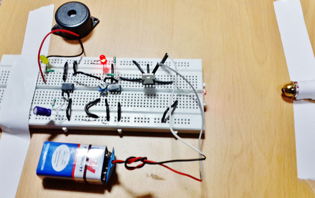
Security is main concern for various buildings, houses and offices. There are a variety of security alarms available in market which uses various types of technology for intruder detection like infrared sensors, motion sensors, ultrasonic sensors, laser sensors, etc. Previously we have also built some security alarm circuits like this PIR sensor based motion detector and burglar alarm circuit. In this circuit tutorial we are going to build a laser security alarm system which uses a laser light and a laser light detector circuit. It gets activated when someone crosses it.
Circuit Components
- IC LM358
- 555 Timer IC
- Laser light
- 150 Ohm, 10K Resistor
- 10 K POT
- 220uF capacitor
- LDR
- Breadboard
- 9 Volt Battery and Connector
- LED
Laser Security System Circuit Diagram and Explanation
In this laser security alarm circuit we have used LM358 Dual Comparator IC for comparing voltages coming from LDR. Comparator is configured as Non-inverting mode and one 10K potentiometer is connected at its non-inverting terminal. An LDR is used for detecting light or laser light with respect to ground through a 10K resistor. And the midpoint of LDR and resistor is directly connected to inverting terminal of comparator. A red LED is connected at output pin of comparator for indicating intruder detection. A mono-stable multi-vibrator is also used for activating buzzer and LED for a time period. And a 9 volt battery is used for powering the circuit.
Working of Laser Security Alarm Circuit
In this circuit we have set reference voltages of comparators by using potentiometer, we can say this sensitivity of the circuit. Comparator is configured in non-inverting mode. In this system we have placed laser light and LDR facing each other, so laser light continuously falls on LDR. Due to this a potential difference generated across the non-inverting pin of comparator, then comparator compare this potential difference with reference voltage and generate a digital output as HIGH. Before this we have configured 555 timer in monostable mode so we it required a LOW trigger pulse at its trigger pin to activate buzzer and LED. So we applied output of comparator at trigger pin of 555 timer. Even comparator’s output is HIGH when laser lights falls on LDR so at this time buzzer and LED are deactivated. When someone crosses the laser light due to this LDR lost the laser light and generates a different potential difference across the same comparator terminal. Then comparator generates an output as LOW. Due to this LOW signal 555 timer gets a LOW trigger pulse and activates buzzer and LED for a time periods that is defined by R1 and C1 at 555 timer circuit.

Main component of this circuit is LDR which detects dark and light. LDR is a light dependent resistor which changes his resistance according to the light. When light falls on the LDR surface, it reduces its resistance and when no light resistance of LDR become Maximum. Understand more about working of LDR in this Dark Detector Circuit.
The 555 timer time calculation formula in mono-stable mode is:
Time period T is given by :
T = 1.1 R1 * C1
Where T is time in seconds, R1 is resistance in ohm and C1 is capacitor in farads
To demonstrate this project we have used a small toy laser light.
Comments
Working distance
To what maximum distance could the laser and ldr be set apart?
need an information about the kit
Can I get this laser security alarm kit and where can I get it?
Why we can not use battary
Why we can not use battary without 7805
i tried making this project
i tried making this project but it doesn't work .. the voltage that goes to the buzzer terminals are both negative... how can i fix this sir?
How are you telling that the
How are you telling that the voltage is negative to the buzzer? Check your connection please
How to increase the time of
How to increase the time of buzzer for 1 min
Can you please add HD photo of breadboard circuit.
Please add photo of circuits
PCB layout please
Can you sent me the pcb layout of this circuit, please....
i did the whole circuit in
i did the whole circuit in proteus,i'm not getting the sound and the led's are not glowing.please help
i did the whole circuit in
i did the whole circuit in proteus,i'm not getting the sound and the led's are not glowing.please help
i did the whole circuit in
i did the whole circuit in proteus,i'm not getting the sound and the led's are not glowing.please help
why when i constuct it into
why when i constuct it into the proteus and when i want to run it, my proteus suddenly shut off?
i contruct this circuit in
i contruct this circuit in proteus, but how to make the buzzer and D2 turn on? how do we interupt the LDR in proteus?


The sensor used here is an LDR, if light falls on it, the resistance of it will decrease hence it can detect light