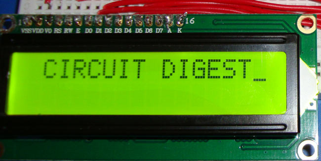
Display units are the most important output devices in embedded projects and electronics products. 16x2 LCD is one of the most used display unit. 16x2 LCD means that there are two rows in which 16 characters can be displayed per line, and each character takes 5X7 matrix space on LCD. In this tutorial we are going to connect 16X2 LCD module to the 8051 microcontroller (AT89S52). Interfacing LCD with 8051 microcontroller might look quite complex to newbies, but after understanding the concept it would look very simple and easy. Although it may be time taking because you need to understand and connect 16 pins of LCD to the microcontroller. So first let's understand the 16 pins of LCD module.
We can divide it in five categories, Power Pins, contrast pin, Control Pins, Data pins and Backlight pins.
Category | Pin NO. | Pin Name | Function |
Power Pins | 1 | VSS | Ground Pin, connected to Ground |
2 | VDD or Vcc | Voltage Pin +5V | |
Contrast Pin | 3 | V0 or VEE | Contrast Setting, connected to Vcc thorough a variable resistor. |
Control Pins | 4 | RS | Register Select Pin, RS=0 Command mode, RS=1 Data mode |
5 | RW | Read/ Write pin, RW=0 Write mode, RW=1 Read mode | |
6 | E | Enable, a high to low pulse need to enable the LCD | |
Data Pins | 7-14 | D0-D7 | Data Pins, Stores the Data to be displayed on LCD or the command instructions |
Backlight Pins | 15 | LED+ or A | To power the Backlight +5V |
16 | LED- or K | Backlight Ground |
All the pins are clearly understandable by their name and functions, except the control pins, so they are explained below:
RS: RS is the register select pin. We need to set it to 1, if we are sending some data to be displayed on LCD. And we will set it to 0 if we are sending some command instruction like clear the screen (hex code 01).
RW: This is Read/write pin, we will set it to 0, if we are going to write some data on LCD. And set it to 1, if we are reading from LCD module. Generally this is set to 0, because we do not have need to read data from LCD. Only one instruction “Get LCD status”, need to be read some times.
E: This pin is used to enable the module when a high to low pulse is given to it. A pulse of 450 ns should be given. That transition from HIGH to LOW makes the module ENABLE.
There are some preset command instructions in LCD, we have used them in our program below to prepare the LCD (in lcd_init() function). Some important command instructions are given below:
| Hex Code | Command to LCD Instruction Register |
| 0F | LCD ON, cursor ON |
| 01 | Clear display screen |
| 02 | Return home |
| 04 | Decrement cursor (shift cursor to left) |
| 06 | Increment cursor (shift cursor to right) |
| 05 | Shift display right |
| 07 | Shift display left |
| 0E | Display ON, cursor blinking |
| 80 | Force cursor to beginning of first line |
| C0 | Force cursor to beginning of second line |
| 38 | 2 lines and 5×7 matrix |
| 83 | Cursor line 1 position 3 |
| 3C | Activate second line |
| 08 | Display OFF, cursor OFF |
| C1 | Jump to second line, position 1 |
| OC | Display ON, cursor OFF |
| C1 | Jump to second line, position 1 |
| C2 | Jump to second line, position 2 |
Circuit Diagram and Explanation
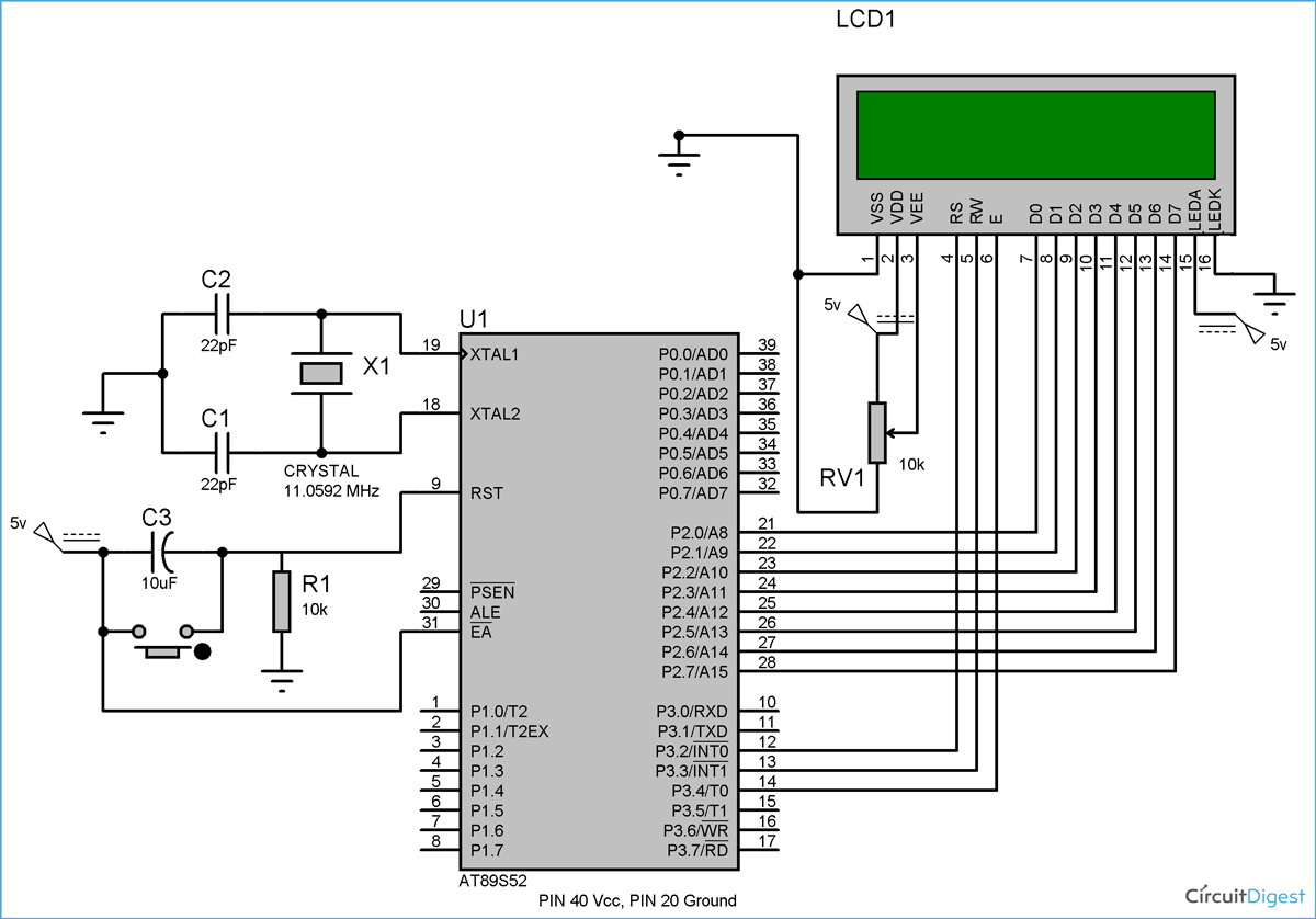
Circuit diagram for LCD interfacing with 8051 microcontroller is shown in the above figure. If you have basic understanding of 8051 then you must know about EA(PIN 31), XTAL1 & XTAL2, RST pin(PIN 9), Vcc and Ground Pin of 8051 microcontroller. I have used these Pins in above circuit. If you don’t have any idea about that then I recommend you to read this Article LED Interfacing with 8051 Microcontroller before going through LCD interfacing.
So besides these above pins we have connected the data pins (D0-D7) of LCD to the Port 2 (P2_0 – P2_7) microcontroller. And control pins RS, RW and E to the pin 12,13,14 (pin 2,3,4 of port 3) of microcontroller respectively.
PIN 2(VDD) and PIN 15(Backlight supply) of LCD are connected to voltage (5v), and PIN 1 (VSS) and PIN 16(Backlight ground) are connected to ground.
Pin 3(V0) is connected to voltage (Vcc) through a variable resistor of 10k to adjust the contrast of LCD. Middle leg of the variable resistor is connected to PIN 3 and other two legs are connected to voltage supply and Ground.
Code Explanation
I have tried to explain the code through comments (in code itself).
As I have explained earlier about command mode and data mode, you can see that while sending command (function lcd_cmd) we have set RS=0, RW=0 and a HIGH to LOW pulse is given to E by making it 1, then 0. Also when sending data (function lcd_data) to LCD we have set RS=1, RW=0 and a HIGH to LOW pulse is given to E by making it 1 to 0. Function msdelay() has been created to create delay in milliseconds and called frequently in the program, it is called so that LCD module can have sufficient time to execute the internal operation and commands.
A while loop has been created to print the string, which is calling the lcd_data function each time to print a character until the last character (null terminator- ‘\0’).
We have used the lcd_init() function to get the LCD ready by using the preset command instructions (explained above).
Complete Project Code
// Program for LCD Interfacing with 8051 Microcontroller (AT89S52)
#include<reg51.h>
#define display_port P2      //Data pins connected to port 2 on microcontroller
sbit rs = P3^2;  //RS pin connected to pin 2 of port 3
sbit rw = P3^3;  // RW pin connected to pin 3 of port 3
sbit e =  P3^4;  //E pin connected to pin 4 of port 3
void msdelay(unsigned int time)  // Function for creating delay in milliseconds.
{
    unsigned i,j ;
    for(i=0;i<time;i++)
    for(j=0;j<1275;j++);
}
void lcd_cmd(unsigned char command)  //Function to send command instruction to LCD
{
    display_port = command;
    rs= 0;
    rw=0;
    e=1;
    msdelay(1);
    e=0;
}
void lcd_data(unsigned char disp_data)  //Function to send display data to LCD
{
    display_port = disp_data;
    rs= 1;
    rw=0;
    e=1;
    msdelay(1);
    e=0;
}
 void lcd_init()    //Function to prepare the LCD  and get it ready
{
    lcd_cmd(0x38);  // for using 2 lines and 5X7 matrix of LCD
    msdelay(10);
    lcd_cmd(0x0F);  // turn display ON, cursor blinking
    msdelay(10);
    lcd_cmd(0x01);  //clear screen
    msdelay(10);
    lcd_cmd(0x81);  // bring cursor to position 1 of line 1
    msdelay(10);
}
void main()
{
    unsigned char a[15]="CIRCUIT DIGEST";    //string of 14 characters with a null terminator.
    int l=0;
    lcd_init();
    while(a[l] != '\0') // searching the null terminator in the sentence
    {
        lcd_data(a[l]);
        l++;
        msdelay(50);
    }
}
Comments
Please refer this: Getting Started with 8051 Microcontroller
What is the difference b\w 8051 and 89s52
liquid crystal display is working but it is not display anything like circuit digest.
how can i fix that sir
programme uploading done
and programme is correct
but it is not work
pls tell any idea sir
Check your circuit connections again.
Agree with you harish kumar
If you got the solution kindly share with us
hey..!!! your lcd interfacing code wwas really helpful.
can you please provide me a code for interfacing LCD in 4 Bit Mode.
sir i m not getting the display on lcd it is running but there is display of CIRCUIT DIGEST
Thanku for ur explanation and code.Can u tell me how to store multiple strings into LCD?
sir, i want program for the ardino uno adc program
sir, i used this code it is working while simulation(Proteus s/w) in laptop....but in hardware not displaying words in LCD.....it's showing blocks...plz tell what might be the problem..
i will love to be part of you guys
the program can be erased on at89s52
Hello circuit digest!
Can I use blue character display instead of green.
hey circuit digest...
how can display fix value on LCD interfacing with 8051..and give me assembly language
........plz
The above video shows lcd interface on bread board
Can this project be shown on general purpose board???
Also on pcb???
Very useful article


what kind of programmer did you use and which software