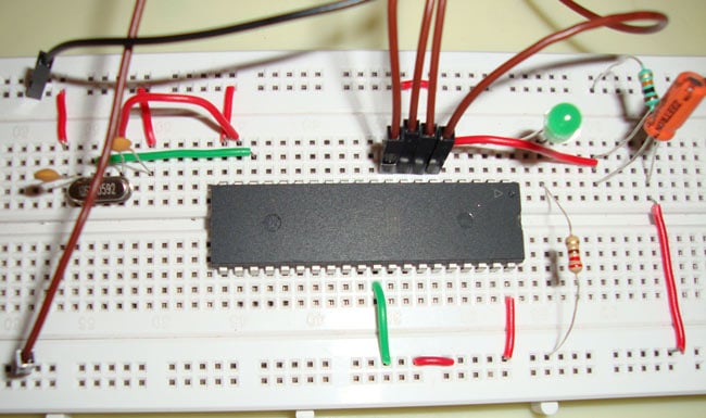
LED interfacing is the first thing one would try to do while getting started with any microcontroller. So here in this tutorial, we are going to interface an LED with an 8051 microcontroller, and we will write a C Program to blink the LED. We have used a very popular microcontroller, AT89S52, of the 8051 family, by ATMEL. LED interfacing with 8051 microcontroller is the foundational project for anyone beginning their journey in embedded systems. The LED interfacing with 8051 project teaches essential concepts like GPIO programming, port configuration, and basic input-output operations.
Before going into detail, we should get a brief idea about the microcontroller AT89S52. It is a 40-pin microcontroller, and has 4 ports (P0, P1, P2, P3), each port has 8 pins. We can consider each port as an 8-bit register, from the software point of view. Each pin has one Input/output line, which means every pin can be used for input as well as for output, i.e. to read data from some device, like a sensor or to provide its output to some output device. Some pins have Dual functionality, which has been mentioned in brackets in the Pin Diagram below. Dual functionality, like for interrupts, counters, timers, etc.
Table of Contents
LED Interfacing with 8051
| Parameter | Specification | Description |
| Microcontroller | AT89S52 (8051 family) | 40-pin DIP package with 4 I/O ports |
| LED Connection | Port 1, Pin 0 (P1.0) | Any port pin can be used |
| Crystal Frequency | 11.0592 MHz | Standard frequency for serial communication |
| Logic Level | Negative Logic | 0 = LED ON, 1 = LED OFF |
| LED Resistor | 330Ω - 1kΩ | Current limiting resistor |
| Operating Voltage | 5V DC | Standard TTL voltage level |
| RAM | 256 Bytes | For variable storage during execution |
| Flash Memory | 8KB | For program storage (EEPROM) |
What is the 8051 Microcontroller AT89S52? Pin Configuration & Features
Before diving into LED interfacing with 8051 microcontroller, let's understand the AT89S52 chip. The interfacing diagram of LED with 8051 starts with understanding the microcontroller's architecture.
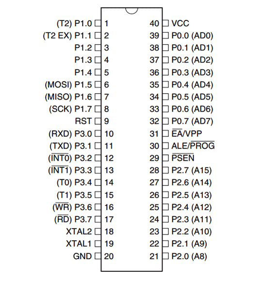
AT89S52 has two types of memory: first is RAM, which has 256 Bytes of memory, and second is EEPROM (Electronically Erasable and Programmable Read Only Memory), which has 8k bytes of memory. RAM is used to store the data during the execution of a program, and EEPROM is used to store the Program itself. EEPROM is the flash memory which we used to burn the program into.
Components Required for LED Interfacing with 8051
S.No | Component | Value/Type | Quantity | Purpose |
1 | Microcontroller | AT89S52 | 1 | Main processing unit |
2 | LED | 5mm (Red/Green) | 1 | Output indicator |
3 | Resistor | 330Ω | 1 | LED current limiting |
4 | Crystal Oscillator | 11.0592 MHz | 1 | Clock generation |
5 | Capacitor | 22pF | 2 | Crystal oscillation |
6 | Capacitor | 10µF | 1 | Reset circuit |
7 | Resistor | 10kΩ | 1 | Reset pull-up |
8 | Push Button | SPST | 1 | Manual reset |
9 | Power Supply | 5V DC | 1 | System power |
10 | Breadboard | Standard size | 1 | Circuit assembly |
11 | Connecting Wires | 22 AWG | As needed | Connections |
LED Interfacing with 8051 Circuit Diagram Explained
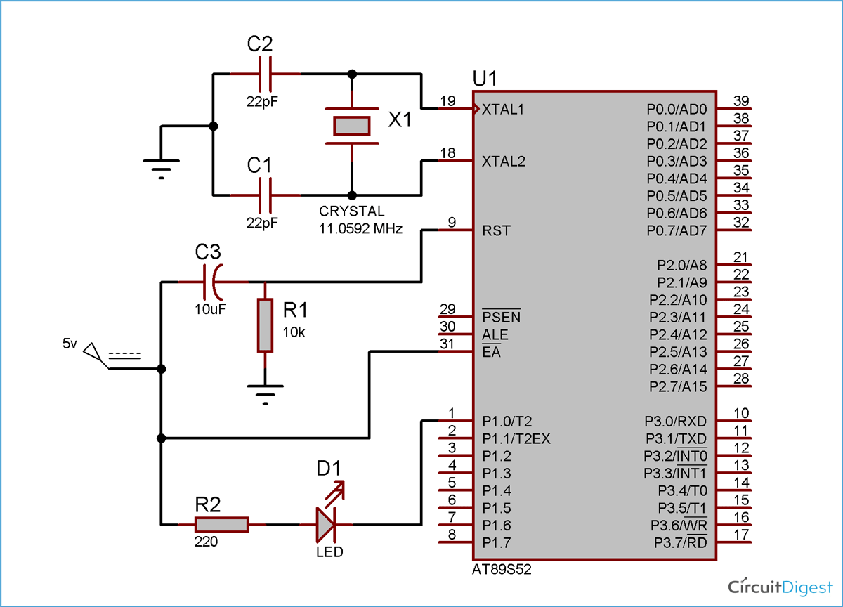
We are using pin one of port 1 to connect the LED. In embedded C programming, we can access PIN 1 of port 1 by using P1_0. We have connected a crystal oscillator of 11.0592MHz frequency to the PINs 19 and 18, i.e. XTAL1 and XTAL2. A crystal oscillator is used to generate clock pulses, and a clock pulse is used to provide the means for timing calculation, which is mandatory to synchronise all the events. These types of crystals are used in almost every modern digital equipment, like in computers, watches, etc. The most commonly used Crystal is quartz. It's a resonant oscillator circuit, and capacitors are used to oscillate the crystal, so we have connected 22pf capacitors here. You can read about “resonant circuits” to know more.
The circuit diagram for LED interfacing with 8051 microcontroller 89S52 is shown in the above figure. Pin 31 (EA) is connected to Vcc, which is an active low pin. This should be connected to Vcc when we are not using any external memory. Pin 30(ALE) and pin 29 (PSEN) are used to connect the microcontroller to the external memory, and Pin 31 tells the microcontroller to use external memory when connected to Ground. We are not using any external memory, so we connected Pin31 to Vcc. The LED interfacing with 8051 circuit diagram illustrated above shows all essential connections for this project. This interfacing diagram of LED with 8051 includes the microcontroller, crystal oscillator circuit, reset mechanism, and LED connection following negative logic principles.
Pin 9 (RST) is the reset PIN, used to reset the microcontroller and program it again, starting from the beginning. It resets the microcontroller when connected to HIGH. We have used standard reset circuitry, a 10k ohm resistor and a 1uF Capacitor to connect the RST pin. Since our LED interfacing with 8051 circuit diagram uses only internal memory (EA = Vcc), these pins serve no purpose and can be left floating or connected to ground through 10kΩ resistors to prevent noise pickup.
Now the interesting part here is that we connect the LED in reverse, meaning the negative leg with the microcontroller PIN, because microcontrollers don’t provide enough power to glow an LED, so here the LED run on the negative logic like when, pin P1_0 is 1 then LED will be tuned OFF and when pin output is 0 then LED will be turned ON. When the PIN output is 0, it behaves like ground, and the LED glows. For basic LED interfacing with 8051 projects, internal memory suffices, so we connect EA to Vcc. A push button connected in parallel provides manual reset capability, useful during development and debugging of the LED interfacing with 8051 project.
AT89S52 Pin Configuration for LED Interfacing
| Pin Number | Pin Name | Connection | Function |
| 40 | Vcc | +5V | Power supply positive |
| 20 | GND | Ground | Power supply ground |
| 1 | P1.0 | LED (cathode) | Digital output to LED |
| 18, 19 | XTAL2, XTAL1 | 11.0592MHz Crystal | Clock oscillator input |
| 31 | EA | Vcc | Internal memory enable (active low) |
| 9 | RST | Reset Circuit | System reset (active high) |
| 29 | PSEN | No connection | Program store enable (for external memory) |
| 30 | ALE | No connection | Address latch enable (for external memory) |
LED Interfacing with 8051 Program in Embedded C
Header REGX52.h has been included to include the basic register definitions. There are many types of variables and constants in embedded C, like int, char, unsigned int, float, etc, you can learn them easily. Here we are using an unsigned int whose range is from 0 to 65535. We are using a “for loop” for creating a delay, so that the LED will be ON for some time (P1_0=0, negative LED logic) and OFF (P1_0=1, negative LED logic) for a delayed time. Generally, when the “for loop” runs for 1275 times, it gives a delay of 1ms, so we have created a ‘delay’ function for creating DELAY and called it from the main program (main()). We can pass DELAY time (in ms) while calling the “delay” function from the main function. In the program, “While(1)” means that the program will execute infinitely. In LED interfacing with 8051 program in embedded C, we access this pin using the syntax P1_0. The LED's cathode (negative terminal) connects to the microcontroller pin, while the anode connects to Vcc (+5V) through a 330Ω current-limiting resistor. The following LED interfacing with 8051 program in embedded C demonstrates how to blink an LED connected to Port 1, Pin 0. However, for learning basic LED interfacing with 8051, software delays are perfectly adequate and help understand timing concepts.
I am briefly explaining how a 1275 times run of the “for” loop gives a delay of 1ms:
In 8051, 1 machine cycle requires 12 crystal pulses to execute, and we have used a 11.0592MHz crystal.
So time required for 1 machine cycle: 12/11.0592 = 1.085us
So 1275*1.085=1.3ms, 1275 times of “for” loop gives nearly 1ms of delay.
The exact time delay produced by the “C” program is very difficult to compute, when measuring from oscilloscope (CRO), for (j=0;j<1275;j++) gives a delay of nearly 1ms. This simple interfacing of LED with 8051 microcontroller demonstrates core embedded programming concepts: GPIO control, timing generation, and hardware-software interaction—skills applicable to complex projects like motor control, sensor interfacing, and communication systems.
So we can understand by simply interfacing an LED with an 8051 microcontroller, that with simple coding, we can interact and control the hardware through software (programming) using a microcontroller. Also, we can manipulate each port and pin of the microcontroller through programming.
Technical Summary and GitHub Repository
Explore the complete technical overview of this project, including circuit design, code explanation, and implementation details. Access the full source code and files on the GitHub repository for easy reference and customisation.
Frequently Asked Questions: LED interfacing with 8051
⇥ 1. What does it mean to LED interface the 8051 microcontroller?
When we talk about LED interfacing, we mean controlling and connecting an LED using the microcontroller's GPIO pins. The LED is connected to any port pin with the addition of a resistor to limit the current, and then you program the pin for HIGH logic to turn the LED ON, and LOW logic to turn the LED OFF. This is a basic exercise and is designed to help familiarise you and have a fundamental understanding of hardware interfacing of software with embedded systems, understanding digital OUT.
⇥ 2. Why use negative logic in LED interfacing with 8051?
Negative logic is used because the 8051 microcontroller output pins can source only a small amount of current (1-2 mA) to drive an LED adequately, but they can handle a lot more current (10-15 mA) when sinking. In a negative logic interface, the LED cathode connects directly to the microcontroller pin output; when the pin is outputting logic LOW or 0V, the pin acts as a ground, allowing current to flow from Vcc through the LED to the pin, thus making the LED illuminate brightly.
⇥ 3. Which port is the best to LED interface the 8051 microcontroller?
Basically, the best port to use for LED interfacing with 8051 is Port 1 (P1), because it has built-in internal pull-up resistors and will not need any external components to provide a resistor for the LED. But essentially, any of the ports can be used as all four ports (P0, P1, P2, P3) can drive an LED. However, port 0 will need an external pull-up resistor to be used. However, all four ports (P0, P1, P2, P3) can be used. Port 0 requires external pull-up resistors (10kΩ). Similarly, Port 2 and Port 3 should be used very carefully due to their dual functions, like an address/data bus and serial communication.
⇥ 4. Why is an 11.0592 MHz crystal used in LED interfacing with 8051?
The 11.0592 MHz crystal is commonly used because it's perfectly divisible by the standard baud rates of 9600, 4800, and 2400 bps with zero error in serial communication—something important in future UART projects. For simple LED interfacing in 8051, other frequencies such as 12 MHz, 10 MHz, or 16 MHz can also be used. This crystal will provide the clock signal that is needed for all the timing-related operations, including the delay calculation for the blinking pattern of the LEDs.
⇥ 5. How do I calculate the delay time for LED blinking in embedded C?
Delay calculation depends on crystal frequency and machine cycles. With an 11.0592 MHz crystal, one machine cycle = 12 crystal pulses / 11,059,200 Hz = 1.085 microseconds. For a 1 millisecond delay, approximately 921 machine cycles are theoretically needed. However, due to for-loop instruction overhead (initialisation, comparison, increment, jump), empirical testing shows 1,275 loop iterations produce approximately 1ms delay. Formula: delay_time = loop_iterations × machine_cycle_time × instructions_per_iteration.
⇥ 6. Can I connect multiple LEDs to an 8051 microcontroller?
Yes, we can connect, via current-limiting resistors (330Ω - 1kΩ), a total of 8 LEDs per port × 4 ports = 32 LEDs for connection directly to the ports of the microcontroller - P0, P1, P2, and P3. If there are going to be more than 32 LEDs, use LED driver ICs such as ULN2003, use multiplexing strategies, such as using a transistor array or shift register like 74HC595, for any increase of output capacity beyond available GPIO pins.
⇥ 7. What is the maximum current a port pin of the 8051 microcontroller can source or sink?
It is critical to point out that the majority of the 8051 port pins can safely sink 15-20mA and at most only source 1-2mA. The total current used by the port pins cannot exceed 71mA for all 8 pins connected to a single port, and the total current used by all port pins cannot exceed 150mA for the entire microcontroller. To illuminate standard LEDs correctly, 10-20mA of current is required, so the appropriate current limiting resistor must be utilised to ensure no damage occurs to the port pins and reliable operation of the LED, which may last a long time.
Conclusion
LED interfacing with 8051 microcontroller is the fundamental approach to start your embedded systems learning journey, since all of your future projects, from such a simple one to the more complicated LED-Matrix applications, will be based on the same fundamental ideas. In this detailed tutorial, you've learned the whole process of interfacing of LED with the 8051 microcontroller AT89S52. The tutorial material included circuit design, part selection, pin connections, and embedded C programming. The LED interfacing with 8051 circuit diagram and LED interfacing with 8051 program in embedded C in this tutorial constitute a great starting point for understanding GPIO control, timing generation, negative logic implementations, and all physical software/hardware interactions. You learned how to calculate delay, sink current versus source current, the operation of a crystal oscillator and reset circuit design through this basic interfacing diagram of an LED with 8051, and now this umbrella of knowledge ultimately gives you confidence with more involved microcontroller projects.
Innovative LED Display Projects
Explore a collection of innovative LED display projects built using Arduino, featuring dynamic designs with MAX7219 dot matrix modules, colourful NeoPixel LED strips, and P10 LED panels for creating digital notice boards and visual displays.
Interfacing MAX7219 LED Dot Matrix Display with Arduino
So in this article, we decided to shed some light on this cheap and easy-to-use display called the Dot Matrix Display, and for this project, we will be interfacing Arduino with the Dot Matrix Display.
Interfacing WS2812B Neopixel LED Strip with Arduino
So, in this Arduino interfacing tutorial series, we are going to look at how to interface such LEDs with Arduino. We will be interfacing the WS2812B LEDs, which are also known as NeoPixels.
LED Display Board using P10 LED Matrix Display and Arduino
This comprehensive guide will teach you how to make an LED display board using Arduino with a P10 LED matrix module, creating a professional-grade digital notice board perfect for commercial and educational applications.
Complete Project Code
#include <REGX52.h>
delay(unsigned int y){
    unsigned int i,j;
for(i=0;i<y;i++){
    for(j=0;j<1275;j++){}
}
}

main(){
    while(1){
        delay(100);
        P1_0 = 0;
        delay(100);
        P1_0 = 1;
    }
}
Comments
You must check this Tutorial : Getting Started with 8051 Microcontroller
jayanth
i followed your exact circuit and my code is correct when i tried to debug i could see it is working fine. do i need to pull out reset pin to make my led glow?
i feel like there is a small step i m missing out...
can you please elaborate your explanation after I arranged circuit and given power supply ....
then do my led glow directly or after dumping hex file? or after dumping hex file do i need to pull out reset pin?
Thanks
Vijay
Led should glow just after the dumping of HEX file, try adding a Reset button like here 7 Segment Display Interfacing with 8051 Microcontroller , and press the reset button couple of times.
sir can you provide me project of how to send a text to an led board...plz sir help me i am in confusion ...
I' m compiling the program for AT89S52 microcontrller. when I do build target than generate the "return value". where i do write return value ?
what is the output voltage of the At89s52 when using a 5v power supply
if the IC is going to work with 5v DC supply then the same is the o/p ?
Will the circuit works if I do not use reset circuit?
I soldered the RX and TX Pins (UART) of the AT89S52 to a MCP2221. Now I want to programm the microcontroller, what things do I need?
How many LED's (0.35watts, 3.2 - 3.4v) can support this circuit board , I mean 1000 or 1500 ... Please tell Me if any one know....




Hi
I am new to this embedded programming hope you will help me...
i am using progisp s.w to flash into MC, there i found out connection pins are different from yours as you are using 8051 loader s.w and i connected as per your directions but i m getting an error "chip enable program error". what i feel is circuit pins of hardware kit may be different and differs from s.w to s.w.
please let me know where i m doing wrong.
thanks
vijay