

This is our 8th tutorial of Learning PIC microcontrollers using MPLAB and XC8. We have come up all the way from installing MPLABX to using a LCD with PIC MCU. If you are new here, then look at previous tutorials where you can learn timers, blinking LED, interfacing LCD etc.. You can find all our PIC Tutorials here. In our last tutorial we saw how we can generate Custom characters with our 16*2 LCD display, now let us equip our self with another type of display module called the 7-segment display and interface it with PIC Microcontroller.
Although 16x2 LCD is much more comfortable than 7-segment display but there are few scenarios where a 7-segment display would come in handier than a LCD display. LCD suffers from the drawback of having low character size and will be overkill for your project if you are just planning to display some numeric values. 7-segments also have the advantage against poor lighting condition and can be viewed from lager angles than a normal LCD screen. So, let us start knowing it.
7-Segment and 4-Digit 7-Segment Display Module:
7 Segment Display has seven segments in it and each segment has one LED inside it to display the numbers by lighting up the corresponding segments. Like if you want the 7-segment to display the number "5" then you need to glow segment a,f,g,c, and d by making their corresponding pins high. There are two types of 7-segment displays: Common Cathode and Common Anode, here we are using Common Cathode seven segment display. Learn more about 7 segment display here.
Now we know how to display our desired numeric character on a single 7-segment display. But, it is pretty evident that we would need more than one 7-segment display to convey any information that is more than one digit. So, in this tutorial we will be using a 4-digit 7-Segment Display Module as shown below.
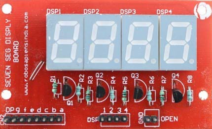
As we can see there are Four Seven Segment Displays connected together. We know that each 7-segment module will have 10 pins and for 4 seven segment displays there would be 40 pins in total and it would be hectic for anyone to solder them on a dot board, so I would highly recommend anyone to buy a module or make your own PCB for using a 4-digit 7-segment display. The connection schematic for the same is shown below:
To understand how 4-digit seven segment module works we have to look into the above schematics, as shown the A pins of all four display is connected to gather as one A and the same for B,C.... upto DP. So, basically if trigger A on, then all four A's should go high right?
But, that does not happen. We have additional four pins from D0 to D3 (D0, D1, D2 and D3) which can be used to control which display out of the four should go high. For example: If I need my output to be present only on the second display then only D1 should be made high while keeping other pins (D0, D2, and D3) as low. Simply we can select which display has to go active using the pins from D0 to D3 and what character to be display using the pins from A to DP.
Connecting 4-Digit Seven Segment Module with PIC Microcontroller:
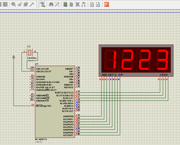
Here we have used PIC microcontroller PIC16F877A and the schematic for the circuit is shown below.

We have 12 output pins from the module out of which 8 is used to display the characters and four is used to select one display out of four. Hence all the 8 character pins are assigned to PORTD and the display selection pins are assigned to first four pins of PORTC.
Note: Ground pin of the module should also be connected to the ground of the MCU which is not shown here.
Programming using PIC16F877A:
Now, that we know how this module actually works, let us learn how to program PIC16F877A to make it display a 4 digit number. Let us increment a variable from 0 to 1000 and print it on the 7-segment display. Launch the MPLABX program and create new project, let us start with the configuration bits.
#pragma config FOSC = HS        // Oscillator Selection bits (HS oscillator)
#pragma config WDTE = OFF       // Watchdog Timer Enable bit (WDT disabled)
#pragma config PWRTE = ON       // Power-up Timer Enable bit (PWRT enabled)
#pragma config BOREN = ON       // Brown-out Reset Enable bit (BOR enabled)
#pragma config LVP = OFF        // Low-Voltage (Single-Supply) In-Circuit Serial Programming Enable bit (RB3 is digital I/O, HV on MCLR must be used for programming)
#pragma config CPD = OFF        // Data EEPROM Memory Code Protection bit (Data EEPROM code protection off)
#pragma config WRT = OFF        // Flash Program Memory Write Enable bits (Write protection off; all program memory may be written to by EECON control)
#pragma config CP = OFF         // Flash Program Memory Code Protection bit (Code protection off)
As usual we use the set configuration bits window to set these bits. If you are not sure what they mean then visit the LED blinking tutorial here.
Next let us define the output pins for toggling between each digit of the display.
//***Define the signal pins of all four displays***//
#define s1 RC0
#define s2 RC1
#define s3 RC2
#define s4 RC3
//***End of definition**////
Here the pins RC0, RC1, RC2 and RC3 are used for selecting between the four digits of our 7-segment display module. These pins are defined as s1, s2, s3 and s4 respectively.
Next let us jump into void main(), inside which we have the following variable declaration:
int i = 0; //the 4-digit value that is to be displayed
int flag =0; //for creating delay
unsigned int a,b,c,d,e,f,g,h; //just variables
unsigned int seg[]={0X3F, //Hex value to display the number 0
                    0X06, //Hex value to display the number 1
                    0X5B, //Hex value to display the number 2
                    0X4F, //Hex value to display the number 3
                    0X66, //Hex value to display the number 4
                    0X6D, //Hex value to display the number 5
                    0X7C, //Hex value to display the number 6
                    0X07, //Hex value to display the number 7
                    0X7F, //Hex value to display the number 8
                    0X6F  //Hex value to display the number 9
                   }; //End of Array for displaying numbers from 0 to 9
Here the variables i and flag are used for storing the values to be displayed and creating a delay respectively. The unsigned integer variables a to h are used to break the four digit numbers into single digits and store them (which will be explained later here).
One key thing to note here is the "seg[]" array declaration. In this program we are using a new data type called Array. Array is nothing but a collection of similar data-type values. Here, we have used this array to store all the equivalent hex values for displaying a number from 0 to 9.
The address of the array always starts from zero. So this array will have the hex value of a numeric number (0-9) stored in the address which is same as that of the number as shown below
|
Variable: |
seg[0] |
seg[1] |
seg[2] |
seg[3] |
seg[4] |
seg[5] |
seg[6] |
seg[7] |
seg[8] |
seg[9] |
|
Hex Code: |
0X3F |
0X06 |
0X5B |
0X4F |
0X66 |
0X6D |
0X7C |
0X07 |
0X7F |
0X6F |
|
Eq. Numeric number: |
0 |
1 |
2 |
3 |
4 |
5 |
6 |
7 |
8 |
9 |
So simply, if you want to display the number 0 on your 7-segment you can call seg[0], likewise if you want to display the number 6 you just have to use seg[6].
To understand how the HEX value was actually obtained let us look into the below table. The equivalent HEX value for each decimal number is stored in the array so that it can be called to display one particular number.
Now, let us move on to the next part of the code which is the I/O configuration:
//*****I/O Configuration****//
TRISC=0X00;
PORTC=0X00;
TRISD=0x00;
PORTD=0X00;
//***End of I/O configuration**///
I/ O configuration is simple because all the pins on our 7-segment are output pins, and the connections are shown in the circuit diagram above, so simply declare them as outputs and initialize them to zero.
Now let us jump into our infinite loop (while(1)). Here we have to split the value of "i" into four digits and display them on the 7-segment. First let us start by splitting the value on "i"
//***Splitting "i" into four digits***//
a=i%10;//4th digit is saved here
b=i/10;
c=b%10;//3rd digit is saved here
d=b/10;
e=d%10; //2nd digit is saved here
f=d/10;
g=f%10; //1st digit is saved here
h=f/10;
//***End of splitting***//
By using simple modulus and division operation the 4 digit number (i) is separated into individual numbers. In our case let us take an example where the value of "i" is 4578. Then at the end of this process the variable g=4, e=5, c=7, and a=8. So now it will be easy to display each digit by simply using that variable.
PORTD=seg[g];s1=1; //Turn ON display 1 and print 4th digit
__delay_ms(5);s1=0;     //Turn OFF display 1 after 5ms delay
PORTD=seg[e];s2=1; //Turn ON display 2 and print 3rd digit
__delay_ms(5);s2=0;     //Turn OFF display 2 after 5ms delay
PORTD=seg[c];s3=1; //Turn ON display 3 and print 2nd digit
__delay_ms(5);s3=0;     //Turn OFF display 3 after 5ms delay
PORTD=seg[a];s4=1; //Turn ON display 4 and print 1st digit
__delay_ms(5);s4=0;     //Turn OFF display 4 after 5ms delay
This is the actual place where the MCU talks with the 7-segment. As we know we can display only one digit at a time, but we have four digits to be displayed and only if all the four digits are On the complete four digit number will be visible for the user.
So, how do we go with this?
Lucky for us our MCU is very much faster than a human eye, so what we actually do: we display one digit at a time but we do it very fast as shown above.
We select one digit display it wait for 5ms so that the MCU and 7-segment can process it and then turn off that digit and move on to the next digit and do the same till we reach the last digit. This delay of 5ms cannot be observed by a human eye and all the four digits appeared to be On at the same time.
That is it, finally we just increment the value of displayed digit using a delay as shown below
if(flag>=100) //wait till flag reaches 100
{
    i++;flag=0; //only if flag is hundred "i" will be incremented
}
flag++; //increment flag for each flash
The delay is used so that the time taken for changing from one number to another is long enough for us to notice the change.
The complete code is given below and the process is also explained in the Video at the end.
Hardware Setup and Testing:
As always let us simulate the program using Proteus before we actually go with our hardware. If the simulation is successful you should see something like this
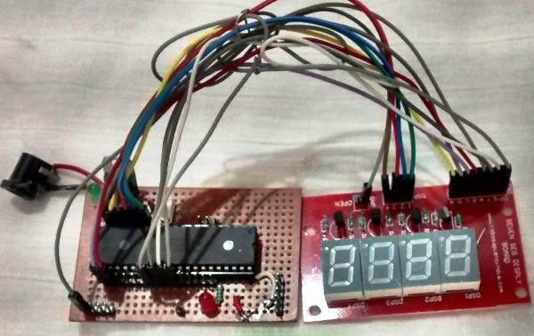
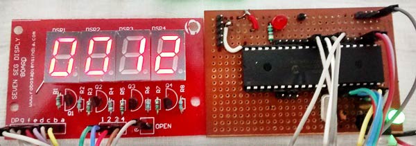
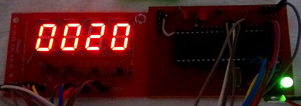
This project does not have any complicated hardware setup, we are again using the same PIC Microcontroller board which we have created in LED blinking Tutorial. Simply connect the 7-segment Module with your PIC Microcontroller board according the connection diagram. Once you are done with the connections, simply dump the code using your PicKit 3 programmer and that is it enjoy your output.
Complete Project Code
// CONFIG

#pragma config FOSC = HS        // Oscillator Selection bits (HS oscillator)

#pragma config WDTE = OFF       // Watchdog Timer Enable bit (WDT disabled)

#pragma config PWRTE = ON       // Power-up Timer Enable bit (PWRT enabled)

#pragma config BOREN = ON       // Brown-out Reset Enable bit (BOR enabled)

#pragma config LVP = OFF        // Low-Voltage (Single-Supply) In-Circuit Serial Programming Enable bit (RB3 is digital I/O, HV on MCLR must be used for programming)

#pragma config CPD = OFF        // Data EEPROM Memory Code Protection bit (Data EEPROM code protection off)

#pragma config WRT = OFF        // Flash Program Memory Write Enable bits (Write protection off; all program memory may be written to by EECON control)

#pragma config CP = OFF         // Flash Program Memory Code Protection bit (Code protection off)
// #pragma config statements should precede project file includes.

// Use project enums instead of #define for ON and OFF.
#include <xc.h>
//***Define the signal pins of all four displays***//

#define s1 RC0

#define s2 RC1

#define s3 RC2

#define s4 RC3

//***End of definition**////
void main()

{

unsigned int a,b,c,d,e,f,g,h; //just variables

int i = 0; //the 4-digit value that is to be displayed

int flag =0; //for creating delay
unsigned int seg[]={0X3F, //Hex value to display the number 0

                    0X06, //Hex value to display the number 1

                    0X5B, //Hex value to display the number 2

                    0X4F, //Hex value to display the number 3

                    0X66, //Hex value to display the number 4

                    0X6D, //Hex value to display the number 5

                    0X7C, //Hex value to display the number 6

                    0X07, //Hex value to display the number 7

                    0X7F, //Hex value to display the number 8

                    0X6F  //Hex value to display the number 9

                   }; //End of Array for displaying numbers from 0 to 9

//*****I/O Configuration****//

TRISC=0X00;

PORTC=0X00;

TRISD=0x00;

PORTD=0X00;

//***End of I/O configuration**///
#define _XTAL_FREQ 20000000
while(1)

{

  //***Splitting "i" into four digits***//

a=i%10;//4th digit is saved here

b=i/10;

c=b%10;//3rd digit is saved here

d=b/10;

e=d%10; //2nd digit is saved here

f=d/10;

g=f%10; //1st digit is saved here

h=f/10;

//***End of splitting***//
PORTD=seg[g];s1=1; //Turn ON display 1 and print 4th digit

__delay_ms(5);s1=0;     //Turn OFF display 1 after 5ms delay

PORTD=seg[e];s2=1; //Turn ON display 2 and print 3rd digit

__delay_ms(5);s2=0;     //Turn OFF display 2 after 5ms delay

PORTD=seg[c];s3=1; //Turn ON display 3 and print 2nd digit

__delay_ms(5);s3=0;     //Turn OFF display 3 after 5ms delay

PORTD=seg[a];s4=1; //Turn ON display 4 and print 1st digit

__delay_ms(5);s4=0;     //Turn OFF display 4 after 5ms delay
if(flag>=100) //wait till flag reaches 100

{

    i++;flag=0; //only if flag is hundred "i" will be incremented

}

flag++; //increment flag for each flash

}

}
Comments
Yes you can!!
Hi eengine,
Yes you can use two 7-segment displays to run on a single PIC MCU. You just need another 12 I/O pins to connect the 7-segment display and repeat the same process
Hi Godwin,
Hi Godwin,
If you have made it with LCD then its quite straight forward to replace it with an 7-segment Display. For example if you have saved the voltage value in the variable "Voltage" simply use the above program and replace the variable i with "Voltage". Also prevent it from incrementing.
This is the dirtiest way to make it work. But, once you get this understand the program and re-write your complete code.
I want to control 4 seven
I want to control 4 seven segments displays by using two buttons that are able to increase and decrease them. How should I do?
It will be very much similar
It will be very much similar to this project.
Once you understand the project, you can connect two push buttons to any two I/O pins and re-write your code in such a way that when first push button is pressed variable "i" is increased and when the second button is pressed the variable "i" is decreased.
SECURITY LOCK
what do i need to do if i have a keypad number 0-9 and if i want to press 8 in the keypad number 8 should be reflected to the 7 segment and if i input 3, 6,8 the numbers reflected in the 4 digit seven segment display should be 8,3,6,8 and when i input this number a greed led will be on. can u help me?
Yes of course I can help you,
Yes of course I can help you, where are you facing problem ? Just interface a keypad read the number form it dialpy it on the 7-segment. It should be easy, where areyou facing probelm herE?
I want to make simple harness tester using 7 segment LED display
My requirement is I need a circuit board with 3 number of 104 pin D- sub connector connected circuit.
when i touch the ground of circuit to one of the pin of D- sub 7 segment led should display that pin number.
if any one is made this type of project please share the details .
The circuit does not work in ISIS.
the circuit did not work in ISIS when i tried to simulate the same exact thing. it worked by seeting flag under 100. what could be the issue?
Proteus Simulation is not working
Plz help me in havind the Proteus simulation.
In my hardware, 7 segment
In my hardware, 7 segment pins is in different port like:Seg A to SegD (in RA0 to RA4) SegE(in RF1) SegF (RG4) SegG(RG3). I can count 0 to 9 with setting bits one by one. I need to count 0-9999 but ı can't store values. How can ı do that for my specs?
Your display no longer available..using a plain 4 digit 7 seg
Hi,
Did this with a 4 digit 7 segment common anode display. Had to use the compliment of each digit for it to be correct, but does work as advertised.
common cathode
Tried with a common cathode and the digitss were ok, but had to put digit pin low for display and high for off.
In case this is unclear for
In case this is unclear for someone, here is an explanation:
//***Splitting "i" into four digits***//
a=i%10;  // i is divided by 10 and "a" becomes the digit behind the comma.
making clock
Sir intrested in making this clock can you please give me the hex file for the combination
thanks
vijayan

Can i do this for a 2 digits 7 segments as well? how do i do it?