
Relays are frequently used in our electronics applications specially when we need to drive high loads from microcontroller circuits. So in this DIY project, we make a 4-Channel Relay Driver Circuit to be used in relay based applications. In-here we have designed an isolated PCB for 4 relays to operate 4 AC appliances at a time. We have put a three pin screw terminal blocks (NC, Nuteral, NO) for connecting appliances.
Components Required:
- SPDT relay 12v -4
- 817 Optocoupler -4
- Transistor BC547 -4
- SMD LEDs -5
- PCB (ordered from EasyEDA) -1
- Terminal Block 3 pin -5
- 1N4007 Diode -1
- 1k Resistor -9
- Burg sticks male -1
- Power supply
- Microcontroller or Arduino for demonstration
- Connecting wire
Relay Driver Circuit Explanation:
In this 4-Channel Relay Driver Circuit we have used an optocoupler whic his triggered by active LOW signal, to trigger the NPN transistor which further drives the relay. Here we have used 12v 10Amp relay in this PCB board, but you can also use 5v relays.

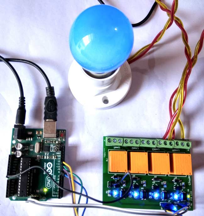
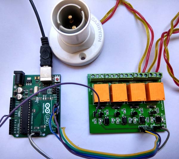
Working and Demonstration:
For demonstrating the working of this Relay Module, we have used an Arduino Uno board for controlling relays. All four relays are connected with Arduino at 8,9,10 and 11th pins (In1, In2, In3, and In4), and 1 12v adapter is used for powering the circuit. We have connected 220VAC bulb at the terminal block of the PCB board and AC supply is also applied to the board.
Below is the Arduino Code which we have used to demonstrate this Relay module:
#define rly1 8
#define rly2 9
#define rly3 10
#define rly4 11

void setup()
{
  pinMode(rly1, OUTPUT);
  pinMode(rly2, OUTPUT);
  pinMode(rly3, OUTPUT);
  pinMode(rly4, OUTPUT);
  delay(2000);
}

void loop()
{
    digitalWrite(rly1, HIGH);
    digitalWrite(rly2, HIGH);
    digitalWrite(rly3, HIGH);
    digitalWrite(rly4, HIGH);
    delay(2000);
    digitalWrite(rly1, LOW);
    digitalWrite(rly2, LOW);
    digitalWrite(rly3, LOW);
    digitalWrite(rly4, LOW);
    delay(2000);
}
Also check the Video at the end of this article.
Circuit and PCB Design using EasyEDA:
To design this Relay Driver Circuit, we have chosen the online EDA tool called EasyEDA. We have previously used EasyEDA many times and found it very convenient to use compared to other PCB fabricators. After designing the PCB, we can order the PCB samples by their low cost PCB fabrication services. They also offer component sourcing service where they have a large stock of electronic components and users can order their required components along with the PCB order.
While designing your circuits and PCBs, you can also make your circuit and PCB designs public so that other users can copy or edit them and can take benefit from there, we have also made our whole Circuit and PCB layouts public for this Relay Driver Module, check the below link:
https://easyeda.com/circuitdigest/RelayBoard-d3f1fbcfc99540738b4f76aceef8882b
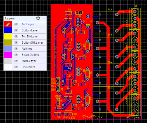
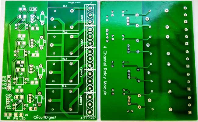
Below is the Snapshot of Top layer of PCB layout from EasyEDA, you can view any Layer (Top, Bottom, Topsilk, bottomsilk etc) of the PCB by selecting the layer form the ‘Layers’ Window.
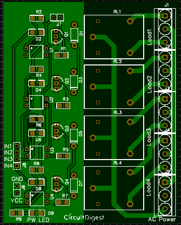
You can also view the PCB, how it will look after fabrication using the Photo View button in EasyEDA:
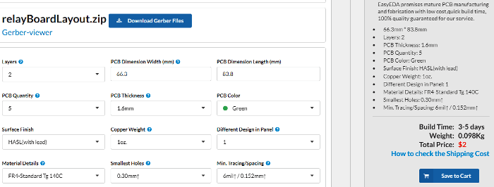
Calculating and Ordering Samples online:
After completing the design of PCB, you can click the icon of Fabrication output above. Then you will access the page PCB order to download Gerber files of your PCB and send them to any manufacturer, it’s also a lot easier (and cheaper) to order it directly in EasyEDA. Here you can select the number of PCBs you want to order, how many copper layers you need, the PCB thickness, copper weight, and even the PCB color. After you have selected all of the options, click “Save to Cart” and complete your order, then you will get your PCBs a few days later. And you may go with your local PCB vendors too with Gerber output of PCB layout. They are fabricating the PCB at very low rate which $2.
After few days of ordering PCB’s I got the PCB samples
Soldering: after getting these pieces we have mounted all the required components over the PCB, and connected it with Arduino for demonstration.
Comments
Sir, your creative ideas are
Sir, your creative ideas are very helpful for us but your explanation is not very good please make it good (this is a request)........
How to make it latching?
You need a constant signal, I want to have a latching relay.
Single high pulse for ON then a high pulse for OFF.
Ralph
use a 555 timer as schmitt trigger
If you want to latch it with two high pulses, then using a 555 timer is bistable mode will help. You have to design this additional circuitry.
Sir i am trying to implement
Sir i am trying to implement fingerprint based voting system with arduino but I am having a problem in it my doubt is being listed in the forum if you please kindly help me with it.Sorry for commenting here.

in your schematics, you showed two +5v, i am bit confused.. Could you explain?