

In this project we are going to make a vibration alert system with ATMEGA8 microcontroller. This can also be used as a theft alert system, for that we are going to interface tilt sensor with ATMEGA8. A tilt sensor is shown in below figure.
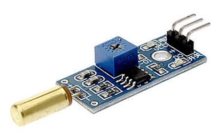
We can see there is a cylinder in the picture, in that cylinder there will be a freely moving metal ball. At the bottom of the cylinder there will be two metal contacts. So when the sensor is moved the free falling ball makes contact with conductors at bottom making a short circuit. This short circuit will be sensed by op-amp in the control circuit. As a response to the tilt the op-amp shows a high output.
We are going to give the tilt sensor signal to ATMEGA8 for appropriate response.
Components Required
Hardware: ATMEGA8 microcontroller, power supply (5v), AVR-ISP PROGRAMMER, 1000uF capacitor, LED, 220Ω resistor, LDR (Light Dependent Resistor), 10KΩ resistor, 1KΩ resistor, 2n3906 transistor, buzzer, Any motion sensor module (HC-SR501), 1KΩresistor(5 pieces), Buttons (5 pieces), 2WATT LED, TIP122 transistor.
Software: Atmel studio 6.1, progisp or flash magic.
Circuit Diagram and Explanation

As shown in circuit, there is no need to connect an external crystal here. Because the ATMEGA works on internal 1MHz, Resistor-Capacitor oscillator on default. Only when the accuracy of clock is needed, as application of high precision counting, external crystal is attaches. When the controller is first bought, it is fused to work on internal crystal by default.
The ATMEGA8 fuse bits are not touched here, as we don’t need accuracy the default 1MHZ internal clock is enough in this circuit.
Once there is vibration the sensor sends high pulse to ATMEGA8. Once high pulse is received the controller will be programmed to send a alert by turning the buzzer ON which makes noise.
After that only the authorized persons can turn off the alarm. There will be 5 keys interfaced to ATMEGA with this there will be 4999 combinations possibility. On all those combinations only one combination can turn off the alarm. This correct code will be programmed in the controller. So only the person with code can turn OFF alarm which was set during vibration.
Hence we will have a THEFT ALERT system by using ATmega8 Microcontroller.
Complete Project Code
#include <avr/io.h>//header to enable data flow control over pins
#define F_CPU 1000000//telling controller crystal frequency
#include <util/delay.h>//header to enable delay function in program
int check();
volatile int alarm = 0;
volatile int chec = 0;
int main(void)
{
DDRD = 0;//PORTD as input
DDRC = 0;//PORTC as input
DDRB = 0xFF;//PORTB as output
while(1)
{
if ((bit_is_clear(PIND,0)))
{
alarm=1;//after vibration set ALARM bit
}
if (bit_is_clear(PINC,4))
{
if (bit_is_clear(PINC,2))
{
 if (bit_is_clear(PINC,1))
{
if ((bit_is_set(PINC,0))&&(bit_is_set(PINC,3)))
{
 _delay_ms(220);
check();
//if only keys5,3 and 2 are pressed execute CHECK loop
}
}
}
}
if (alarm==1)//If ALARM bit is set
{
PORTB |=(1<<PINB0);//turn on LED
PORTB &=~(1<<PINB1);//turn on BUZZER
}
if (alarm==0)//if ALARM bit is not set
{
PORTB |=(1<<PINB1);//turn OFF LED
PORTB &=~(1<<PINB0);//turn OFF buzzer
}
}
}
int check()
{
if (bit_is_clear(PINC,4))
{
if (bit_is_clear(PINC,2))
{
if (bit_is_clear(PINC,1))
{
if ((bit_is_set(PINC,0))&&(bit_is_set(PINC,3)))
{
if (chec==1)
{
alarm=0;
//if the buttons are stills pressed after 5sec put reset ALARM bit.
}
if (chec==0)
{
for (int i=0;i<15;i++)
{
_delay_ms(220);
//check for bits clearance after 5 sec
}
chec=1;
check();
}
}
else
{
chec=0;
}
}
}
}
}
Comments
alert system
Would you please send me the detailed circuit using ATMega8 with abilty of sending SMS.
It will be very helpful for me.
Thanks.
Omid
can you please tell me the
can you please tell me the applications of it ..

Dear Sir,
Could you please send me the detail circuit using- AT Mega 8, it will be very helpful for me.
Thanks
somnath.