
Mobile phone is a revolutionary invention of the century. It was primarily designed for making and receiving calls & text messages, but it has become the whole world after the Smart phone comes into the picture. In this project we are building a home automation system, where one can control the home appliances, using the simple GSM based phone, just by sending SMS through his phone. In this project, no Smart phone is needed, just the old GSM phone will work to switch ON and OFF any home electronic appliances, from anywhere. You can also check some more Wireless Home Automation projects here: IR Remote Controlled Home Automation using Arduino, Bluetooth Controlled Home Automation along with DTMF Based Home Automation, PC Controlled Home Automation using Arduino.
If you are completely new to GSM module, you can also consider reading our Arduino GSM Module tutorial to understand the basics before proceeding with this project.
Working Explanation
In this project, Arduino is used for controlling whole the process. Here we have used GSM wireless communication for controlling home appliances. We send some commands like “#A.light on*”, “#A.light off*” and so on for controlling AC home appliances. After receiving given commands by Arduino through GSM, Arduino send signal to relays, to switch ON or OFF the home appliances using a relay driver.
Circuit Components:
- Arduino UNO
- GSM Module
- ULN2003
- Relay 5 volt
- Bulb with holder
- Connecting wires
- Bread board
- 16x2 LCD
- Power supply
- Cell phone
Here we have used a prefix in command string that is “#A.”. This prefix is used to identify that the main command is coming next to it and * at the end of string indicates that message has been ended.
When we send SMS to GSM module by Mobile, then GSM receives that SMS and sends it to Arduino. Now Arduino reads this SMS and extract main command from the received string and stores in a variable. After this, Arduino compare this string with predefined string. If match occurred then Arduino sends signal to relay via relay driver for turning ON and OFF the home appliances. And relative result also prints on 16x2 LCD by using appropriate commands.
Here in this project we have used 3 zero watt bulb for demonstration which indicates Fan, Light and TV.
Below is the list of messages which we send via SMS, to turn On and Off the Fan, Light and TV:
|
S.no. |
Message |
Operation |
|
1 |
#A.fan on* |
Fan ON |
|
2 |
#A.fan off* |
Fan OFF |
|
3 |
#A.light on* |
Light ON |
|
4 |
#A.light off* |
Light OFF |
|
5 |
#A.tv on* |
TV ON |
|
6 |
#A.tv off* |
TV Off |
|
7 |
#A.all on* |
All ON |
|
8 |
#A.all off* |
All OFF |
GSM Module:
GSM module is used in many communication devices which are based on GSM (Global System for Mobile Communications) technology. It is used to interact with GSM network using a computer. GSM module only understands AT commands, and can respond accordingly. The most basic command is “AT”, if GSM respond OK then it is working good otherwise it respond with “ERROR”. There are various AT commands like ATA for answer a call, ATD to dial a call, AT+CMGR to read the message, AT+CMGS to send the sms etc. AT commands should be followed by Carriage return i.e. \r (0D in hex), like “AT+CMGS\r”. We can use GSM module using these commands:
ATE0 - For echo off
AT+CNMI=2,2,0,0,0 <ENTER> - Auto opened message Receiving. (No need to open message)
ATD<Mobile Number>; <ENTER> - making a call (ATD+919610126059;\r\n)
AT+CMGF=1 <ENTER> - Selecting Text mode
AT+CMGS=”Mobile Number” <ENTER> - Assigning recipient’s mobile number
>>Now we can write our message
>>After writing message
Ctrl+Z send message command (26 in decimal).
ENTER=0x0d in HEX
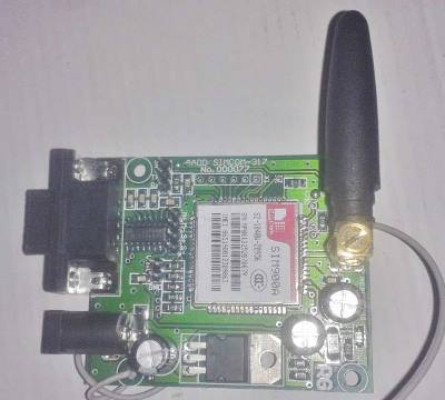
The SIM900 is a complete Quad-band GSM/GPRS Module which delivers GSM/GPRS 850/900/1800/1900MHz performance for voice, SMS and Data with low power consumption.
Circuit Description
Connections of this GSM based home automation circuit are quite simple, here a liquid crystal display is used for displaying status of home appliances which is directly connected to arduino in 4-bit mode. Data pins of LCD namely RS, EN, D4, D5, D6, D7 are connected to arduino digital pin number 6, 7, 8, 9, 10, 11. And Rx and Tx pin of GSM module is directly connected at Tx and Rx pin of Arduino respectively. And GSM module is powered by using a 12 volt adaptor. 5 volt SPDT 3 relays are used for controlling LIGHT, FAN and TV. And relays are connected to arduino pin number 3, 4 and 5 through relay driver ULN2003 for controlling LIGHT, FAN and TV respectively.

Code Description
In programming part of this project, first of all in programming we includes library for liquid crystal display and then we defines data and control pins for LCD and home appliances.
#include<LiquidCrystal.h>
LiquidCrystal lcd(6,7,8,9,10,11);

#define Fan 3
#define Light 4
#define TV 5

int temp=0,i=0;
int led=13;
After this serial communication is initialized at 9600 bps and gives direction to used pin.
void setup()
{
  lcd.begin(16,2);
  Serial.begin(9600);
  pinMode(led, OUTPUT);
   pinMode(Fan, OUTPUT);
    pinMode(Light, OUTPUT);
     pinMode(TV, OUTPUT);
For receiving data serially we have used two functions one is Serial.available which checks whether any serial data is coming and other one is Serial.read which reads the data that comes serially.
 while (Serial.available())
      {
      char inChar=Serial.read();
After receiving data serially we have stored it in a string and then waiting for Enter.
void serialEvent()
 {
  while(Serial.available())
  {
    if(Serial.find("#A."))
    {
      digitalWrite(led, HIGH);
      delay(1000);
      digitalWrite(led, LOW);
      while (Serial.available())
      {
      char inChar=Serial.read();
      str[i++]=inChar;
      if(inChar=='*')
      {
        temp=1;
        return;
      }
When Enter comes program start to compare received string with already defined string and if string matched then a relative operation is performed by using appropriate command that are given in code.
void check()
{
   if(!(strncmp(str,"tv on",5)))
    {
      digitalWrite(TV, HIGH);
      lcd.setCursor(13,1);
      lcd.print("ON    ");
      delay(200);
    }

   else if(!(strncmp(str,"tv off",6)))
    {
      digitalWrite(TV, LOW);
      lcd.setCursor(13,1);
      lcd.print("OFF    ");
      delay(200);
    }
Complete Project Code
#include<LiquidCrystal.h>
LiquidCrystal lcd(6,7,8,9,10,11);
#define Fan 3
#define Light 4
#define TV 5
int temp=0,i=0;
int led=13;
char str[15];
void setup()
{
  lcd.begin(16,2);
  Serial.begin(9600);
  pinMode(led, OUTPUT);
   pinMode(Fan, OUTPUT);
    pinMode(Light, OUTPUT);
     pinMode(TV, OUTPUT);
  lcd.setCursor(0,0);
  lcd.print("GSM Control Home");
  lcd.setCursor(0,1);
  lcd.print("   Automaton    ");
  delay(2000);
  lcd.clear();
  lcd.print("Circuit Digest");
  delay(1000);
  lcd.setCursor(0,1);
  lcd.print("System Ready");
  Serial.println("AT+CNMI=2,2,0,0,0");
  delay(500);
  Serial.println("AT+CMGF=1");
  delay(1000);
  lcd.clear();
  lcd.setCursor(0,0);
  lcd.print("Fan   Light  TV ");
  lcd.setCursor(0,1);
  lcd.print("OFF    OFF   OFF ");
}
void loop()
{
  lcd.setCursor(0,0);
  lcd.print("Fan   Light  TV");
  if(temp==1)
  {
    check();
    temp=0;
    i=0;
    delay(1000);
  }
}
 void serialEvent()
 {
  while(Serial.available())
  {
    if(Serial.find("#A."))
    {
      digitalWrite(led, HIGH);
      delay(1000);
      digitalWrite(led, LOW);
      while (Serial.available())
      {
      char inChar=Serial.read();
      str[i++]=inChar;
      if(inChar=='*')
      {
        temp=1;
        return;
      }
      }
    }
   }
 }
void check()
{
   if(!(strncmp(str,"tv on",5)))
    {
      digitalWrite(TV, HIGH);
      lcd.setCursor(13,1);
      lcd.print("ON    ");
      delay(200);
    }
   else if(!(strncmp(str,"tv off",6)))
    {
      digitalWrite(TV, LOW);
      lcd.setCursor(13,1);
      lcd.print("OFF    ");
      delay(200);
    }
    else if(!(strncmp(str,"fan on",5)))
    {
      digitalWrite(Fan, HIGH);
      lcd.setCursor(0,1);
      lcd.print("ON   ");
      delay(200);
    }
    else if(!(strncmp(str,"fan off",7)))
    {
      digitalWrite(Fan, LOW);
      lcd.setCursor(0,1);
      lcd.print("OFF    ");
      delay(200);
    }
    else if(!(strncmp(str,"light on",8)))
    {
      digitalWrite(Light, HIGH);
      lcd.setCursor(7,1);
      lcd.print("ON    ");
      delay(200);
    }
    else if(!(strncmp(str,"light off",9)))
    {
      digitalWrite(Light, LOW);
      lcd.setCursor(7,1);
      lcd.print("OFF    ");
      delay(200);
    }
    else if(!(strncmp(str,"all on",6)))
    {
      digitalWrite(Light, HIGH);
      digitalWrite(Fan, HIGH);
      digitalWrite(TV, HIGH);
      lcd.setCursor(0,1);
      lcd.print("ON     ON    ON  ");
      delay(200);
    }
    else if(!(strncmp(str,"all off",7)))
    {
      digitalWrite(Light, LOW);
      digitalWrite(Fan, LOW);
      digitalWrite(TV, LOW);
      lcd.setCursor(0,1);
      lcd.print("OFF   OFF    OFF  ");
      delay(200);
    }
}
Comments
yes, this code will work fine
yes, this code will work fine. uploaded code on the website is complete. copy it and go ahead.
Is it okay sir to use 5v-4
Is it okay sir to use 5v-4 channels relay instead of 5v SPDT relay and a ULN2003 driver?
Cause i've been trying it using your code and a relay module but it doesn't work(still without an Output connected to it).
Gsm home automation
Sir,
I can't see where mobile number was used in code.
this program will not reply
this program will not reply anything so mobile number is not necessary
hi saddam this project in
hi saddam this project in proteus doesnt work
when i dail the number in virtual terminal no responce
it dont receive comands of sms
hey
i'm sorry but i have make the same with the project with serial and it go fine.
with gsm sim908 it don't work i have use tx e rx 0/1 but also other pins with 7/8
can you help mi please
thank's
i had a issue with this code
what is this? is this code need any modification
E:\tim\tim.ino: In function 'void serialEvent()':
E:\tim\tim.ino:54:25: warning: deprecated conversion from string constant to 'char*' [-Wwrite-strings]
if(Serial.find("#A."));
^
I think you should remove
I think you should remove Semicolon from the "if statement"'.
Thanks to your code sir! It's
Thanks to your code sir! It's working but the initial state of the relay module i used is ON, and all of the commands are inverted. How can i correct this sir?
Glad that your project is
Glad that your project is finally worked. You must have connected NC terminal of Relay to the AC appliances, instead of NO, just swap them. Check this article for Relay working.
replay connection
I make this project.but the relay not work properly. please give the information of relay connection.
no signal with tx/rx
hey Jayant
i hope you can help me the project with serial comands go well but no with gsm .
I use sim 908 tx/rx 0/1 load the sketch without gsm and then remove the usb and put gsm on 0 and 1
but nothing
no signal with tx/rx
hey Jayant
i hope you can help me the project with serial comands go well but no with gsm .
I use sim 908 tx/rx 0/1 load the sketch without gsm and then remove the usb and put gsm on 0 and 1
but nothing
send me the complete code
hiii dennis sir .you did this project?.can you please send me the complete code as fast as possible .
my mail id is ashindp916@gmail.com
@Rajendra What do you mean
@Rajendra What do you mean by "relay not working properly", give us more detail. Circuit diagram clearly explains the connections, connect NO and NC terminals of relay properly.
I have same problem.
Also GM's module received the sms in sim card memory but it not sending the sms to arduuno
don't receive sms message
i have the same problem
i think there is an probleme with code comand gsm
hello dennis do you still
hello dennis do you still have the complete code
may you please provide the
may you please provide the code for the Gsm based door unlock system
which allows the user to unlock the door remotely by sending an sms to the gsm module.
thank you
Check this project: Automatic
Check this project: Automatic Door Opener using Arduino and taking use of both of these projects, you can build one and please share with us.
ask about the gsm project
Dear
Sir
I followed the your projects Sir I want to make gsm relay contorl project
But I have questions
Gsm module how can I interface with gsm module?
Ofter set at commends do we need to delete them?
Can I use 3phase motor starter contorl?
Please explain me
Thank you very much
Circut for attiny85 and 12 volt battery and 433mhz tran.
I would like to wire a 12volt battery with a 7502 voltage reg.. and a attiny 85 to get more distance with my 433mhz transmitter
which program do you use to
which program do you use to draw the schematic for the circuit diagram ?
thank you
Proteus with Arduino Library
Proteus with Arduino Library installed.
GSM SIM900A
CAN U PLEASE HELP ME TO SET GSM MODULE (900A)) FOR THE SAME APPLICATION
We have already explained the
We have already explained the setup of GSM in the above project itself. And if you want to know more, we have lot of projects which are using GSM with Arduino, go through this link and check: http://circuitdigest.com/search/node/gsm%20with%20arduino
does this code is same for
does this code is same for 8051 or diffrent if so plz provide me the 8051 code.
this code can only used for
this code can only used for arduino. if u are using 8051 the mode may be different
sir why can't we use serial
sir why can't we use serial.find() everywhere in code instead of string operations
gsm interface not working properly
sir the system works fine for 1st msg but doesnt respond to the next messages. then i have to reset the whole system to execute the message
SIR the program is very help
SIR the program is very help full
Thank you very much
my system does not respond to second sms
sir, i did as prescribed and it is working fine with the serial monitor. but when it comes to gsm module it does not respond to the second message. ie, if i send #A.tv on* for the first time , it works fine... but then the system does not respond to whatever message i send to the gsm module.... have been with this problem for a lot of time... please help me sir..
For toz circuit can i use Gsm
For toz circuit can i use Gsm 2 click
@ashind
@ashind
i m also getting the same error
C:\Users\Home\Documents\Arduino\test11\test11.ino: In function 'void serialEvent()':
C:\Users\Home\Documents\Arduino\test11\test11.ino:143:25: warning: deprecated conversion from string constant to 'char*' [-Wwrite-strings]
if(Serial.find("#A."))
how to get rid of this error??
kindly reply soon
@sneha this is not an error
@sneha this is not an error .this is just a warning....so dnt wrry u will get o/p
Gsm Module is SIM900A, its
Gsm Module is SIM900A, its already given in the description.
The code is not being
The code is not being uploaded.dnt knw y it is happening.does d code need any modification?
no need of any modification
no need of any modification in code.
remove rx and tx pin from arduino before uploading code.
regarding project
hello sir,
how i wan to caotrol 8 bulb how i proceed plzz help me
ULN2003 can drive upto 7
ULN2003 can drive upto 7 Relays, use ULN2803 for 8 Relays. Change the code and connections accordingly.
About GSM Proteus Model
Dear Sir,
Please send the GSM module to my email id. Your site is good and I am beginner. I wanted to learn.
[]
hii sir the above aurdino gsm
hii sir the above aurdino gsm program how to upload and which softaware using .i have upload but some java error is diplay
Use Arduino IDE software
Use Arduino IDE software (Arduino Nightly : https://www.arduino.cc/en/Main/Software) to burn the code into Arduino.
gsm based home automation
Please can you help me i tried to send sms on my gsm but is not turning on any thing what is the problem and sms shows received in my mobile
supply specification
sir im using 12v/2A GSM module. can u please explain the current and voltage supply rating for the whole circuit. can i use 12v 2A adaptor for whole circuite..?
can one use sim800 in place
can one use sim800 in place of sim900?
will any gsm module work with
will any gsm module work with the same code?
Yes, any GSM module should
Yes, any GSM module should work, just check its Tx and Rx connections.
I am doing project "WIRELESS
I am doing project "WIRELESS WEATHER MONITORING SYSTEM"using arduino uno, GSM sim900a, LCD 16x2, temperature and humidity sensor dht11…now I request yourgood self to please provide me a program that will display current temperature and humidity on LCD. also if we send SMS from any mobile number to a mobile number of simcard that is in GSM to send current temperature or humidity it must send back SMS to the mobile number from which it received SMS with current temperature or humidity..
Check this one :Humidity and
Check this one :Humidity and Temperature Measurement using Arduino, and try to integrate the GSM Module.
gsm based home automation
please any one can help me I asked one week before regarding this code not working for me when I send sms to gsm nothing happen even if sms shows received
please please any one can help me is very nice project I need to build it
my email is [] any one can post me working codes
First only try to Interface
First only try to Interface GSM Module with Arduino, check here for Circuits using GSM with Arduino
gsm
i like to share my home automation project.
my project was GSM based home automation system with SMS feedback and gas leakage sms alert system with automatic power shutdown
*when we sent sms to ARDUINO through GSM module. GSM module will sent an feedback sms to owners mobile number
*when smoke is detected by MQ5 the Arduino will sent 3 alert sms to owners mobile number
and will also shunt down the power.
if anybody need this project program pleas contact me
arduino project
Sir i want to do a call based GSM module project on 8051 micro controller to control the door locking system along with other home appliances,
being a new comer i need the complete detail
1) full step what can i do step by step
2) program for 8051
i shall be very thankful to you , looking forward for your kind reply
Hi @ashind .
Hi @ashind .
Your project is interesting.
Please provide your project details like circuits diagram & project code.
want to buy this project
i really love this project...how can i buy it
sir it's not working
sir it's not working
can we use sim900a instead of sim900
Dear saddam great project but
Dear saddam great project but some time GSM turning on leds and some time not. please explain
Please help me with my code
Can someone help me? This is my code.
#include <LiquidCrystal.h>
#include "SIM900.h"
#include "sms.h"
#include <SoftwareSerial.h>
//#include <sms.h>
#include <PString.h>
SMSGSM sms;
boolean started = false;
char buffer[160];
char smsbuffer[160];
char n[20];
//LiquidCrystal lcd(4,2,3,7,8,9);
int buttonState;
int lastButtonState = LOW;
long lastDebounceTime = 0;
long debounceDelay = 50;
boolean st = false;
int buzzer = 12;
void setup() {
//lcd.begin(16, 2);
Serial.begin(9600);
if (gsm.begin(2400))
{
started = true;
}
if (started)
{
delsms();
}
sms.SendSMS("+6xxxxxxxxxx" , "Gas Sensor and GSM module activated");
}
void loop() {
//lcd.setCursor(0, 0);
//lcd.print("Detektor Gas SMS");
int val = analogRead(A0);
val = map(val, 0, 1023, 0, 100);
//lcd.setCursor(0,1);
//lcd.print("Kadar: ");
//lcd.print(val);
//lcd.print("% ");
//code using sensor detection
if (val > 10) {
tone(buzzer,800,500);
delay(1000);
st = true;
}
else st = false;
if (st != lastButtonState) {
lastDebounceTime = millis();
}
if ((millis() - lastDebounceTime) > debounceDelay) {
if (st != buttonState) {
buttonState = st;
if (buttonState == HIGH) {
PString str(buffer, sizeof(buffer));
str.begin();
str.print("Gas Detected! Gas leakage at ");
str.print(val);
str.print("%");
//String a=str;
sms.SendSMS("+6xxxxxxxxxx", buffer);
}
}
}
//code using sms lapor.
lastButtonState = st;
int pos = 0;
if (started)
{
pos = sms.IsSMSPresent(SMS_ALL);
if (pos)
{
sms.GetSMS(pos, n, smsbuffer, 100);
delay(2000);
if (!strcmp(smsbuffer, "lapor"))
{
PString str(buffer, sizeof(buffer));
str.begin();
str.print("Rate of gas leakage currently at ");
str.print(val);
str.print("%");
//String a=str;
sms.SendSMS("+6xxxxxxxxxx", buffer);
}
delsms();
}
}
}
//delete sms yang dihantar
void delsms()
{
for (int i = 0; i < 10; i++)
{
int pos = sms.IsSMSPresent(SMS_ALL);
if (pos != 0)
{
if (sms.DeleteSMS(pos) == 1) {} else {}
}
}
}
I'm using arduino uno, sim900 module, mq2 gas sensor and buzzer to create a gas sensor detector based on sms.
I have to 2 option :
1. The mq2 gas sensor detects and send the result via sms to the number set in the code.
2. We can send a specific string to know the surrounding gas percentage and send the result to the specific number set in the code.
But I want to change the second option to be auto reply to any incoming number. What should I do?
to know more about project
Sir, I want to do the same project by using micro-controller 8051.
As i am new comer i want detail information about it.
program, all steps, if u have any video then it also etc
plz send me on my email.
Thanks, looking forward for your kind reply.
Project feedback
Dear SK,
Very nicely explained project ever I came across. It has created a lot of interest in my son including me. I thank for your sincere and fare sharing of knowledge.
Thnaks a lot.
about circuit diagram
sir if we are using microprocessor there are two circuit diagrams one is for transmitter and another is for receiver but here is only one so is it like combined or what??
Transmitter is our cell phone
Transmitter is our cell phone itself.
Hi im thinking to make this
Hi im thinking to make this project does this works properly?
But ive compiled this code and it is showing some error
Project is working properly,
Project is working properly, please share the Error you are getting.
Bulb does not light up
Sir. I have try Interfacing GSM Module with Arduino, its working fine. But when i try your project. The bulb does not light up when i send sms to gsm. It show that the sim card in the gsm receive the message but it keep resetting itself. Please help me
please help me
please help me
I did all the right connections
I uploaded the source code
But when I send a message
None of the relay switches not
what is the problem?
We have already explained the
We have already explained the setup of GSM in the above project itself. And if you want to know more, we have lot of projects which are using GSM with Arduino, Try to interface GSM first, check: http://circuitdigest.com/search/node/gsm%20with%20arduino
can someone help me pls. I
can someone help me pls. I connected the circuit as shown above. the LCD is ok but it is not responding to the on/off messages. I'm using sim800l. is there any modification in the program? if yes, how do I go about it?
Hello sir, please am using
Hello sir, please am using SIM900A with two sets of pins (6 pins in group and 3 pins also in group), i do not know how to go about the connections since its a bit different from your own module
Check the data sheet of your
Check the data sheet of your Module, you just need to find out serial communication pins Tx, Rx and power supply pins (Vcc and GND) in your GSM module.
can i use arduino mega instead of uno
sir currently i have arduino mega .so can i use mega instead of arduino uno for the same program
??
Hi i am working on project,
Hi i am working on project, appliances control & switching using gsm & bluetooth , can you help?
hye sir , do you create ur
hye sir , do you create ur own relay circuit ? can i have the schematic . i just kind of confuse whether the relay circuit have connection that related to Arduino Uno.
Yes, its custom created Relay
Yes, its custom created Relay Module on Dot board which has ULN2003 on it. It may available in the Market too.

Is this Code really working sir?
I would like to ask for the complete code this sir, i'm interested in making this project sir! Please Send me the the Code sir!