
Mobile phone is a revolutionary invention of the century. It was primarily designed for making and receiving calls & text messages, but it has become the whole world after the Smart phone comes into the picture. In this project we are building a home automation system, where one can control the home appliances, using the simple GSM based phone, just by sending SMS through his phone. In this project, no Smart phone is needed, just the old GSM phone will work to switch ON and OFF any home electronic appliances, from anywhere. You can also check some more Wireless Home Automation projects here: IR Remote Controlled Home Automation using Arduino, Bluetooth Controlled Home Automation along with DTMF Based Home Automation, PC Controlled Home Automation using Arduino.
If you are completely new to GSM module, you can also consider reading our Arduino GSM Module tutorial to understand the basics before proceeding with this project.
Working Explanation
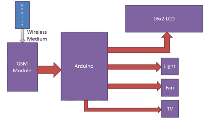
In this project, Arduino is used for controlling whole the process. Here we have used GSM wireless communication for controlling home appliances. We send some commands like “#A.light on*”, “#A.light off*” and so on for controlling AC home appliances. After receiving given commands by Arduino through GSM, Arduino send signal to relays, to switch ON or OFF the home appliances using a relay driver.
Circuit Components:
- Arduino UNO
- GSM Module
- ULN2003
- Relay 5 volt
- Bulb with holder
- Connecting wires
- Bread board
- 16x2 LCD
- Power supply
- Cell phone
Here we have used a prefix in command string that is “#A.”. This prefix is used to identify that the main command is coming next to it and * at the end of string indicates that message has been ended.
When we send SMS to GSM module by Mobile, then GSM receives that SMS and sends it to Arduino. Now Arduino reads this SMS and extract main command from the received string and stores in a variable. After this, Arduino compare this string with predefined string. If match occurred then Arduino sends signal to relay via relay driver for turning ON and OFF the home appliances. And relative result also prints on 16x2 LCD by using appropriate commands.
Here in this project we have used 3 zero watt bulb for demonstration which indicates Fan, Light and TV.
Below is the list of messages which we send via SMS, to turn On and Off the Fan, Light and TV:
|
S.no. |
Message |
Operation |
|
1 |
#A.fan on* |
Fan ON |
|
2 |
#A.fan off* |
Fan OFF |
|
3 |
#A.light on* |
Light ON |
|
4 |
#A.light off* |
Light OFF |
|
5 |
#A.tv on* |
TV ON |
|
6 |
#A.tv off* |
TV Off |
|
7 |
#A.all on* |
All ON |
|
8 |
#A.all off* |
All OFF |
GSM Module:
GSM module is used in many communication devices which are based on GSM (Global System for Mobile Communications) technology. It is used to interact with GSM network using a computer. GSM module only understands AT commands, and can respond accordingly. The most basic command is “AT”, if GSM respond OK then it is working good otherwise it respond with “ERROR”. There are various AT commands like ATA for answer a call, ATD to dial a call, AT+CMGR to read the message, AT+CMGS to send the sms etc. AT commands should be followed by Carriage return i.e. \r (0D in hex), like “AT+CMGS\r”. We can use GSM module using these commands:
ATE0 - For echo off
AT+CNMI=2,2,0,0,0 <ENTER> - Auto opened message Receiving. (No need to open message)
ATD<Mobile Number>; <ENTER> - making a call (ATD+919610126059;\r\n)
AT+CMGF=1 <ENTER> - Selecting Text mode
AT+CMGS=”Mobile Number” <ENTER> - Assigning recipient’s mobile number
>>Now we can write our message
>>After writing message
Ctrl+Z send message command (26 in decimal).
ENTER=0x0d in HEX
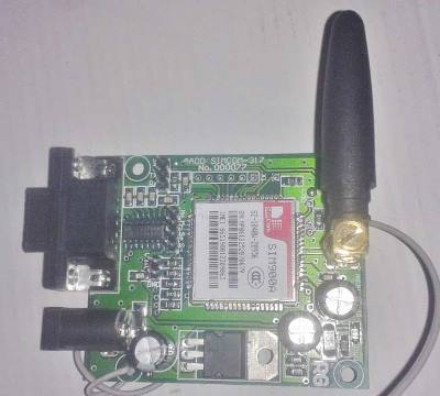
The SIM900 is a complete Quad-band GSM/GPRS Module which delivers GSM/GPRS 850/900/1800/1900MHz performance for voice, SMS and Data with low power consumption.
Circuit Description
Connections of this GSM based home automation circuit are quite simple, here a liquid crystal display is used for displaying status of home appliances which is directly connected to arduino in 4-bit mode. Data pins of LCD namely RS, EN, D4, D5, D6, D7 are connected to arduino digital pin number 6, 7, 8, 9, 10, 11. And Rx and Tx pin of GSM module is directly connected at Tx and Rx pin of Arduino respectively. And GSM module is powered by using a 12 volt adaptor. 5 volt SPDT 3 relays are used for controlling LIGHT, FAN and TV. And relays are connected to arduino pin number 3, 4 and 5 through relay driver ULN2003 for controlling LIGHT, FAN and TV respectively.

Code Description
In programming part of this project, first of all in programming we includes library for liquid crystal display and then we defines data and control pins for LCD and home appliances.
#include<LiquidCrystal.h>
LiquidCrystal lcd(6,7,8,9,10,11);

#define Fan 3
#define Light 4
#define TV 5

int temp=0,i=0;
int led=13;
After this serial communication is initialized at 9600 bps and gives direction to used pin.
void setup()
{
  lcd.begin(16,2);
  Serial.begin(9600);
  pinMode(led, OUTPUT);
   pinMode(Fan, OUTPUT);
    pinMode(Light, OUTPUT);
     pinMode(TV, OUTPUT);
For receiving data serially we have used two functions one is Serial.available which checks whether any serial data is coming and other one is Serial.read which reads the data that comes serially.
 while (Serial.available())
      {
      char inChar=Serial.read();
After receiving data serially we have stored it in a string and then waiting for Enter.
void serialEvent()
 {
  while(Serial.available())
  {
    if(Serial.find("#A."))
    {
      digitalWrite(led, HIGH);
      delay(1000);
      digitalWrite(led, LOW);
      while (Serial.available())
      {
      char inChar=Serial.read();
      str[i++]=inChar;
      if(inChar=='*')
      {
        temp=1;
        return;
      }
When Enter comes program start to compare received string with already defined string and if string matched then a relative operation is performed by using appropriate command that are given in code.
void check()
{
   if(!(strncmp(str,"tv on",5)))
    {
      digitalWrite(TV, HIGH);
      lcd.setCursor(13,1);
      lcd.print("ON    ");
      delay(200);
    }

   else if(!(strncmp(str,"tv off",6)))
    {
      digitalWrite(TV, LOW);
      lcd.setCursor(13,1);
      lcd.print("OFF    ");
      delay(200);
    }
Complete Project Code
#include<LiquidCrystal.h>

LiquidCrystal lcd(6,7,8,9,10,11);
#define Fan 3

#define Light 4

#define TV 5
int temp=0,i=0;

int led=13;
char str[15];

void setup()

{

  lcd.begin(16,2);

  Serial.begin(9600);

  pinMode(led, OUTPUT);

   pinMode(Fan, OUTPUT);

    pinMode(Light, OUTPUT);

     pinMode(TV, OUTPUT);


  lcd.setCursor(0,0);

  lcd.print("GSM Control Home");

  lcd.setCursor(0,1);

  lcd.print("   Automaton    ");

  delay(2000);

  lcd.clear();

  lcd.print("Circuit Digest");

  delay(1000);

  lcd.setCursor(0,1);

  lcd.print("System Ready");

  Serial.println("AT+CNMI=2,2,0,0,0");

  delay(500);

  Serial.println("AT+CMGF=1");

  delay(1000);

  lcd.clear();

  lcd.setCursor(0,0);

  lcd.print("Fan   Light  TV ");

  lcd.setCursor(0,1);

  lcd.print("OFF    OFF   OFF ");

}
void loop()

{

  lcd.setCursor(0,0);

  lcd.print("Fan   Light  TV");

  if(temp==1)

  {

    check();

    temp=0;

    i=0;

    delay(1000);

  }

}
 void serialEvent()

 {

  while(Serial.available())

  {

    if(Serial.find("#A."))

    {

      digitalWrite(led, HIGH);

      delay(1000);

      digitalWrite(led, LOW);

      while (Serial.available())

      {

      char inChar=Serial.read();

      str[i++]=inChar;

      if(inChar=='*')

      {

        temp=1;

        return;

      }

      }

    }

   }

 }
void check()

{

   if(!(strncmp(str,"tv on",5)))

    {

      digitalWrite(TV, HIGH);

      lcd.setCursor(13,1);

      lcd.print("ON    ");

      delay(200);

    }


   else if(!(strncmp(str,"tv off",6)))

    {

      digitalWrite(TV, LOW);

      lcd.setCursor(13,1);

      lcd.print("OFF    ");

      delay(200);

    }


    else if(!(strncmp(str,"fan on",5)))

    {

      digitalWrite(Fan, HIGH);

      lcd.setCursor(0,1);

      lcd.print("ON   ");

      delay(200);

    }


    else if(!(strncmp(str,"fan off",7)))

    {

      digitalWrite(Fan, LOW);

      lcd.setCursor(0,1);

      lcd.print("OFF    ");

      delay(200);

    }


    else if(!(strncmp(str,"light on",8)))

    {

      digitalWrite(Light, HIGH);

      lcd.setCursor(7,1);

      lcd.print("ON    ");

      delay(200);

    }


    else if(!(strncmp(str,"light off",9)))

    {

      digitalWrite(Light, LOW);

      lcd.setCursor(7,1);

      lcd.print("OFF    ");

      delay(200);

    }


    else if(!(strncmp(str,"all on",6)))

    {

      digitalWrite(Light, HIGH);

      digitalWrite(Fan, HIGH);

      digitalWrite(TV, HIGH);

      lcd.setCursor(0,1);

      lcd.print("ON     ON    ON  ");

      delay(200);

    }


    else if(!(strncmp(str,"all off",7)))

    {

      digitalWrite(Light, LOW);

      digitalWrite(Fan, LOW);

      digitalWrite(TV, LOW);

      lcd.setCursor(0,1);

      lcd.print("OFF   OFF    OFF  ");

      delay(200);

    }

}
Comments
What should be the current rating of the 12v adapter ? 1A? 1.5A?
What should be the current rating of the 12 v adapter?
GSM module is powered by
GSM module is powered by using a 12v 1A adaptor.
GSM Module
I have uploaded the code and made the circuit accordingly but now its not connecting with the gsm module allthough all the connections right. i am using SIM900A mini
hye sir
hye sir, ur code work very fine .. thank u very much .
instead of that , can i know how i want to reset each load . not all of it . its like when the load is ON . but when i sent message OFF . its does't off. so i think if i could put switch . and when i push the switch . my load is reset and it off . but i want it to work each load . means in ur code there 3load . so it will be 3 switch for reset .
sorry for asking too much . can i do that and how i want to do it .
please tell me about, what
please tell me about, what softwares that we should use for dumping and all the details
I want references for this to
I want references for this to put them in my project report.
Relay
Relay is On position when arduino powered up ,this will effect at project functioning bcz if power supply gone then all device is automatically shut down, if i connected with AC/DC adapter ,,,how to invert relay on and off in program(CODE) ,,,connection to nc/oc or oc/nc is not a proper solution
All Relays are Off when
All Relays are Off when Arduino powers up initially, please try it out first.
i tried but but relay is not
i tried but but relay is not working,,,,,,every thing is gud and working properly.but when i send msg display showed that device is on but relay is not working with arduino board ,i checked connection many times everything is gud , i also checked this on bread board And DIY PCB ,but relays is not working ,,what can i do sir ,,,and how to invert relays in program, i am using arduina uno,and arduino nano,sim900, please help
Won't work on Softwareserial
Good day!
How I can convert this to SoftwareSerial ?
Please help thank you.
regards,
I wonder why is that when I
I wonder why is that when I monitor the output of SoftwareSerial port it print through Serial monitor a series of -1 and when I try to text a message through cellphone #A.Light on* a 255 number are displayed on serial monitor?
Anybody could help please...
gsm not working
dear sir i am using gsm900a, i made this cicuit, and relay is working properly from serial monitor, but relay is not working from gsm 900a gsm module , relay is not working through send sms
please sir solve this problem
sir
sir in ur code what the mean of this
else if(!(strncmp(str,"all off",7)))
what 7 is representing for ? i bit confuse because there number in each of ur code .
and i face some problem when i change the name . like changing the light to " socketa" . when i sent #A.socketa on* . it does not work . why sir ?
Learn about strncmp function
Learn about strncmp function here: http://www.cplusplus.com/reference/cstring/strncmp/ then ask if you have any doubt.
multi sensor
someone please help me, can I connect two or more smoke sensor ( MQ ) in one board..???
how to recognition or how to give address one by one of sensor , so I can se where sensor has detect smoke.
thank's
GSM CODE
//YOUR CODE NOT WORKING
//=============================//
//THIS IS WORKING CODE TO USE
//=============================//
#include <SoftwareSerial.h>
SoftwareSerial mySerial(10, 11);
#define Fan 3
#define Light 4
#define TV A0
int temp=0,i=0;
int led=13;
char str[15];
void setup()
{
mySerial.begin(9600);
Serial.begin(9600);
pinMode(led, OUTPUT);
pinMode(Fan, OUTPUT);
pinMode(Light, OUTPUT);
pinMode(TV, OUTPUT);
//========================================
Serial.println("GSM Control Home");
Serial.println(" Automaton ");
delay(2000);
Serial.println("System Ready");
//========================================
mySerial.println("AT+CNMI=2,2,0,0,0");
delay(500);
mySerial.println("AT+CMGF=1");
delay(1000);
}
void loop()
{
if(temp==0)
{
serialEvent();
temp=0;
i=0;
delay(1000);
}
}
void serialEvent()
{
while(mySerial.available())
{
if(mySerial.find("#A."))
{
digitalWrite(led, HIGH);
delay(1000);
digitalWrite(led, LOW);
while (mySerial.available())
{
char inChar=mySerial.read();
str[i++]=inChar;
if(inChar=='*')
{
check();
temp=1;
return;
}
}
}
}
}
void check()
{
if(!(strncmp(str,"tv on",5)))
{
digitalWrite(TV, HIGH);
delay(200);
}
else if(!(strncmp(str,"tv off",6)))
{
digitalWrite(TV, LOW);
delay(200);
}
else if(!(strncmp(str,"fan on",5)))
{
digitalWrite(Fan, HIGH);
delay(200);
}
else if(!(strncmp(str,"fan off",7)))
{
digitalWrite(Fan, LOW);
delay(200);
}
else if(!(strncmp(str,"light on",8)))
{
digitalWrite(Light, HIGH);
delay(200);
}
else if(!(strncmp(str,"light off",9)))
{
digitalWrite(Light, LOW);
delay(200);
}
else if(!(strncmp(str,"all on",6)))
{
digitalWrite(Light, HIGH);
digitalWrite(Fan, HIGH);
digitalWrite(TV, HIGH);
delay(200);
}
else if(!(strncmp(str,"all off",7)))
{
digitalWrite(Light, LOW);
digitalWrite(Fan, LOW);
digitalWrite(TV, LOW);
delay(200);
}
}
REPLY
C:\Users\NTSCHYD\Documents\Arduino\gsm\gsm.ino: In function 'void serialEvent()':
C:\Users\NTSCHYD\Documents\Arduino\gsm\gsm.ino:59:25: warning: deprecated conversion from string constant to 'char*' [-Wwrite-strings]
if(Serial.find("#A."))
^
Sketch uses 4,024 bytes (12%) of program storage space. Maximum is 32,256 bytes.
Global variables use 501 bytes (24%) of dynamic memory, leaving 1,547 bytes for local variables. Maximum is 2,048 bytes.
SENT ME THE WHAT WE DID. WHERE WE DO THE PROBLEM
KINDLY SENT REPLY
source code for gsm based home automation
Sir , GSM based home automation is my final year project. So , can you please provide me the source code for the same and full process of making the project and full details of components required for the same?
when i am trying to compile
when i am trying to compile your code , i am getting the error given below. Please help me to resolve this error.
Rebuild target 'Target 1'
assembling STARTUP.A51...
compiling l.c...
l.c(1): warning C318: can't open file 'LiquidCrystal.h'
l.c(2): error C129: missing ';' before 'lcd'
Target not created.
Build Time Elapsed: 00:00:00
i am trying this project but
i am trying this project but i am getting compilation error unable to rename core.a reason permission denied..if please anyone know this answer me ....thanks in advance
Hi i have done this project
Hi i have done this project but my problem is
If i send any message to the gsm the gsm is receiving message but there is no response in Arduino output as well as in lcd display
The 3 outputs are remains in off position even when the msg is received
Please help me
Please read all the previous
Please read all the previous comments, we might have answered them already.
Its Arduino IDE, download it
Its Arduino IDE, download it from here: https://www.arduino.cc/en/main/software
home automation
Sir, how can I provide an input in simulation(now the bulb is off but I need to on through simulation. How? ?)
code not working properly
Sir give me the gsm code to send sms ...code not working
Yes, SIM900A has been used in
Yes, SIM900A has been used in this project.
Sir, can I use sim800 gsm
Sir, can I use sim800 gsm module for this project? Is there any alteration need to be done if I use sim800? Tq
Yes you can use SIM800, just
Yes you can use SIM800, just properly interface it with Arduino. We have used SIM800 here with Arduino, check here.
Please do this project without ULN2003.
Please do this project without ULN2003.
Thanks
Where should i put SerialEvent?
Sir, you have defined a function serialEvent() .... bt you didn't called it anywhere in the program,,, Where should i have to call this funcation?
The code is working
The code is working
So how to commands from gsm module
Plz send me
sir i just doing this project
sir i just doing this project thku sir but i have face some problem on doing this project that is gsm receives the command and lcd it will displays but the load cant operates. .it does not receives the required supply from the Arduino through ic wht can I do sir can u pls tell me
Program not working on my arduino
When i tried to turn on the any equipment through text messag then its isnt working . But when i type the those command on serial monitor then its works .
What to do about this problem ?
Great project
Hello Sir,
Thanks for the project details, it is a great project my dream come true.
When I compile the sketch it gives the following error:
if(Serial.find("#A."))
^
Can you please provide me the coding for 8 channels relays to be controlled;
Fan
Light
TV
Main Door Light
Socket
Lamp
Mis 1
Mis 2
I can handle the electronics part but don't know anything about the coding part.
I will be grateful to you.
Regards,
Ajay
my project is working good
my project is working good but i have one problem that
,when ever i gave a message for first time the output came but, in second time i can't get the output.i have to reset it everytime.please help me.this is my b.tech final year project.
Thank you
code not working
Sir ,
The code is not working properly. The GSM is responding for the first message .after that it is not responding.
And also the code is run fine in only in serial monitor. So I want to make it working full SMS continuously.what should I do for that.
Please ,send me the valid code for project.
I'm working on it
how to led ON or OFF when sms HIGH or LOW pls tell me sir.....
My code is not working Any one can help me then pls solve this code......
#include<GSM.h>
GSM_SMS sms;
int RedLed=11;
int BlueLed=10;
int GreenLed=9;
String msg;
void setup()
{
Serial.begin(9600);
pinMode(RedLed,OUTPUT);
pinMode(BlueLed,OUTPUT);
pinMode(GreenLed,OUTPUT);
digitalWrite(RedLed,LOW);
digitalWrite(BlueLed,LOW);
digitalWrite(GreenLed,LOW);
Serial.println("WelCome New SMS Tutorial...");
}
void loop()
{
char c;
if(sms.available()>0)
{
Serial.println("AT+CMGR");
while(c=sms.read())
msg=msg+c;
Serial.println(c);
msg.toLowerCase();
if(msg=="redon")
{
Serial.println(msg);
digitalWrite(RedLed,HIGH);
delay(20);
}
if(msg=="blueon")
{
Serial.println(msg);
digitalWrite(BlueLed,HIGH);
delay(20);
}
if(msg=="greenon")
{
Serial.println(msg);
digitalWrite(GreenLed,HIGH);
delay(20);
}
}
}
program editing
i dont want to use lcd display so is there any editing needed or can go ahead with same coding. plz help
GSM Module
sir plz tell me the complete name and module number of gsm module
Its SIM900A, further check
Its SIM900A, further check the picture of GSM module in the article above.
regarding number authorization in sim900 module
i am doing the same project as my final year project and i am facing a problem regarding authorizattion of number. so, pls help me
Can I do this same without lcd ?
Currently I didn't purchased LCD. Can I do this project without LCD. Need any editing in the closings? Plz help me.
You can do it without LCD,
You can do it without LCD, remove the code for LCD.
thank you sir for this
thank you sir for this project...code is working....every thing is good...
Hello daniyal asif i am
Hello daniyal asif i am mahesh i have taken this project for irrigation purpose that is to operate solenoid valve instead of bulb,
i have purchased all the components except LCD, but the problem is i am unable to load the program in to Aurdino will you please help me. I am waiting for your replay
thank you
please dania help me , the
please dania help me , the commands is not working
else if(!(strncmp(str,"fan
else if(!(strncmp(str,"fan off",7)))
num cha=7 not 6
Making same project on agriculture irrigation
Dear sir
I have seen ur home automation project,but I needed some help from you for making project on agriculture irrigation system , when electricity come at my farm I need msg on my phone power on ,then m using 3 phase sensor is there if 3phase ok again m need 1 more msg power ok then m given some command like pump 1 on or off,pump 2 on or off m using some valve and operate valve as per my recommendation valve 1 on or off or more valves
where do we put our phone number
frist thanks for code about gsm based home automation but i have question on the arduino code
the mobile number is not mention in arduino code how do we put number of mobile
motor control while recieving call
Sir im doing a project based on motor control ,while recieving a call I need help in coding part.
Disaster management using Arduino
As per subject, I wish everyone will be benefited.
gsm based home automation
thanks for your effort but i have a problem having copied and paste your code to arduino ide i compiled and download, built the circuit as per your instruction but the far i can get is the lcd display fan off, light off tv off.
i sent a msg #A. fan on* but no response i tried with serial monitor too but no change pls advice thanks
can you please tell me which
can you please tell me which relay board is used?
Arduino PC
Hej! The code is working flawless. But I can't figure out how to make the code running without PC. Everything is working OK if the Arduino is connected to PC. If I connect it to an external 5V battery, my SMS will cause nothing to happen. Some additional info will be great!
The problem is most likely
The problem is most likely with your power supply. Make sure all your devices ground are connected together and power it with a reliable 5V supply
I want to ask if the
I want to ask if the smartphone can now be used for GSM
Perfect project.....but did i
Perfect project.....but did i need to install the library for The GSM SIM900a
Module
Iam going to do gsm based
Iam going to do gsm based home automation and home security .is this ppssible
requirements
sir this method used to the microcontroller8051.how to put a program please hlp me sir.
Gsm based home automation
I connect the circuit as shown in fig. and uploaded the same program in the arduino but I didn't get any output
project code
i want relay on or off by a particular mobile number not any other number plz help me the code.
please tell me sir. how i
please tell me sir. how i done on Proteus?
Sir, I am working on this
Sir, I am working on this project but I got difficulties for connection can you send me picture of connections
hi sir where i can put the
hi sir where i can put the mobile number of the system
what is the coding for gsm ?
what is the coding for gsm ? Is it the same as Arduino coding.

can the same program run on arduino mega? ... I can't find uno board in my area but I've a mega board. how can I modify the circuit or /and program to suite mega board?