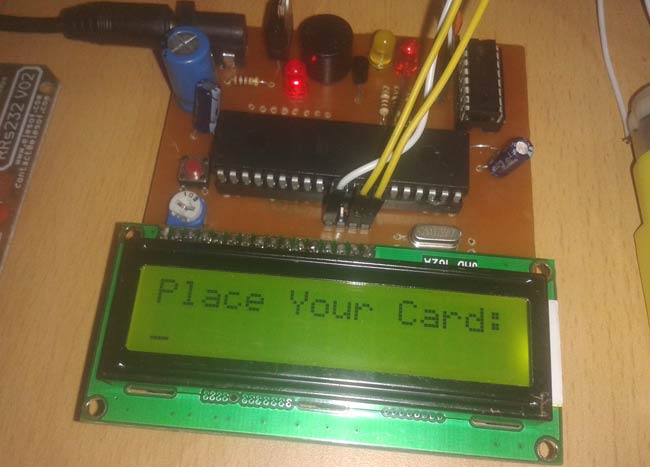
In this RFID based Attendance System project, we will explain you how can we count attendance automatically by using RFID cards. RFID Technology (Radio Frequency Identification and Detection) is commonly used in schools, colleges, office and stations for various purposes to automatically keep a track of people. Here we will count the attendance of an authorized person by using RFID.
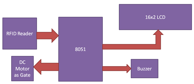
We can divide the complete attendance system into different sections: reader section, control section, driver section and display section. Role of each section is shown in the below block diagram:

Reader Section
This section contains a RFID, which is an electronics device which has two parts - one is RFID Reader and other is RFID tag or Card. When we put RFID tag near to the RFID reader, it reads tag data serially. RFID tag has 12 digit character code in a coil. This RFID is working at baud rate of 9600 bps. RFID uses electromagnet to transfer data from reader to tag or tag to reader.
Control Section:
8051 microcontroller is used for controlling the complete process of this project. Here by using 8051 we are receiving RFID data and sending status or messages to LCD.
Display section:
A 16x2 LCD is used in this project for displaying messages on it.
Driver section:
This section has a motor driver L293D for opening gate and a buzzer with a BC547 NPN transistor for indications.
Working
When a person put their RFID tag to RFID reader then RFID reads tag’s data and send it to 8051 microcontroller and then microcontroller compares this data with defined data or information. If data is matched with defined data then microcontroller increment the attendance by one of the tag’s person and if matched is not occurred then microcontroller shows invalid card on LCD and buzzer is beeping continuously for some time.
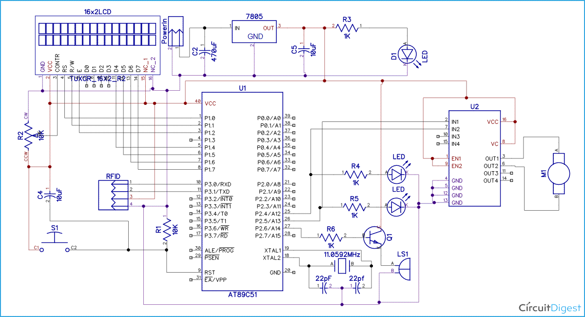
Circuit diagram for RFID bassed attendance system project is shown above. In the circuit, LCD is connected in four bit mode with 8051 microcontroller. LCD’s RS, RW and EN pins are directly connected at PORT 1 pin number P1.0, P1.1 and P1.2. D4, D5, D6 and D7 pins of LCD are directly connected at pin P1.4, P1.5, P1.6 and P1.7 of port 1. Motor driver is connected at PORT pin number P2.4 and P2.5. and buzzer is connected at P2.6 at PORT2. [Also check: LCD Interfacing with 8051 Microcontroller]
Program Explanation
To program for RFID based attedance system, we first need to include header files and defines input and output pin and variables.
#include<reg51.h>
#include<string.h>
#include<stdio.h>

sbit rs=P1^0;
sbit rw=P1^1;
sbit en=P1^2;
sbit m1=P2^4;
sbit m2=P2^5;
sbit buzzer=P2^6;
char i,rx_data[50];
char rfid[13],ch=0;
After this we need to create a function for delay.
 void delay(int itime)
{
    int i,j;
    for(i=0;i<itime;i++)
    for(j=0;j<1275;j++);
}
Then we make some function for LCD and initialize lcd fuction,
void lcd_init(void)
{
    lcdcmd(0x02);
    lcdcmd(0x28);
    lcdcmd(0x0e);
    lcdcmd(0x01);
}
Here we have some function that we have used in our program. In this we have configured 9600bps baud rate at 11.0592MHz Crystal Frequency. We are monitoring the SBUF register for receiving data.
void uart_init()
{
 TMOD=0x20;
 SCON=0x50;
 TH1=0xfd;
 TR1=1;
}

char rxdata()
{
  while(!RI);
    ch=SBUF;
    RI=0;
    return ch;
}
After this in main program, we have initialized lcd and UART and then we reads the output of RFID when any one tag on it. We stores this string in an array and then match with predefined array data.
        lcdcmd(1);
        lcdstring("Place Your Card:");
        lcdcmd(0xc0);
        i=0;
        for(i=0;i<12;i++)
        rfid[i]=rxdata();
        rfid[i]='\0';
        lcdcmd(1);
If match occurrs then controller increases the attendance by one. Else beep buzzer runs continuously and LCD shows invalid card.
        if(strncmp(rfid,"160066A5EC39",12)==0)
        {
            count1++;
            lcdcmd(1);
            lcdstring(" Attendance ");
            lcdcmd(0xc0);
            lcdstring(" Registered");
            delay(200);
            lcdcmd(1);
            lcdstring(" Student1 ");
            lcdcmd(0xc0);
            lcdstring("Attnd. No.: ");
            sprintf(result, "%d", count1);
            lcdstring(result);
PCB Layout
Here is the PCB layout for RFID based Attendance System:
Complete Project Code
#include<reg51.h>

#include<string.h>

#include<stdio.h>

#define lcdport P1

sbit rs=P1^0;

sbit rw=P1^1;

sbit en=P1^2;

sbit m1=P2^4;

sbit m2=P2^5;

sbit buzzer=P2^6;

char i,rx_data[50];

char rfid[13],ch=0;

int count1, count2, count3;

unsigned char result[1];
 void delay(int itime)

{

    int i,j;

    for(i=0;i<itime;i++)

    for(j=0;j<1275;j++);

}

void daten()

{

    rs=1;

    rw=0;

    en=1;

    delay(5);

    en=0;

}
void lcddata(unsigned char ch)

{

    lcdport=ch & 0xf0;

    daten();

    lcdport=(ch<<4) & 0xf0;

    daten();

}

void cmden(void)

{

    rs=0;

    en=1;

    delay(5);

    en=0;

}
void lcdcmd(unsigned char ch)

{

    lcdport=ch & 0xf0;

    cmden();

    lcdport=(ch<<4) & 0xf0;

    cmden();

}
void lcdstring(char *str)

{

    while(*str)

    {

        lcddata(*str);

        str++;

    }

}
void lcd_init(void)

{

    lcdcmd(0x02);

    lcdcmd(0x28);

    lcdcmd(0x0e);

    lcdcmd(0x01);

}
void uart_init()

{

 TMOD=0x20;

 SCON=0x50;

 TH1=0xfd;

 TR1=1;

}

char rxdata()

{

  while(!RI);

    ch=SBUF;

    RI=0;

    return ch;

}
void main()

{

    buzzer=1;

    uart_init();

    lcd_init();

    lcdstring("  RFID Based    ");

    lcdcmd(0xc0);

    lcdstring("Attendance Systm");

    delay(400);

    while(1)

    {

        lcdcmd(1);

        lcdstring("Place Your Card:");

        lcdcmd(0xc0);

        i=0;

        for(i=0;i<12;i++)

        rfid[i]=rxdata();

        rfid[i]='\0';

        lcdcmd(1);

        lcdstring("Your ID No. is:");

        lcdcmd(0xc0);

        for(i=0;i<12;i++)

        lcddata(rfid[i]);

        delay(100);

        if(strncmp(rfid,"160066A5EC39",12)==0)

        {

            count1++;

            lcdcmd(1);

            lcdstring(" Attendance ");

            lcdcmd(0xc0);

            lcdstring(" Registered");

            delay(200);

            lcdcmd(1);

            lcdstring(" Student1 ");

            lcdcmd(0xc0);

            lcdstring("Attnd. No.: ");

            sprintf(result, "%d", count1);

            lcdstring(result);


            m1=1;

            m2=0;

            delay(300);

            m1=0;

            m2=0;

            delay(200);

            m1=0;

            m2=1;

            delay(300);

            m1=0;

            m2=0;

        }


        else if(strncmp(rfid,"160066BD7AB7",12)==0)

            {

            count2++;

            lcdcmd(1);

            lcdstring(" Attendance ");

            lcdcmd(0xc0);

            lcdstring(" Registered");

            delay(200);

            lcdcmd(1);

            lcdstring(" Student2 ");

            lcdcmd(0xc0);

            lcdstring("Attnd. No.: ");

            sprintf(result, "%d", count2);

            lcdstring(result);


            m1=1;

            m2=0;

            delay(300);

            m1=0;

            m2=0;

            delay(200);

            m1=0;

            m2=1;

            delay(300);

            m1=0;

            m2=0;

      }


                else if(strncmp(rfid,"160066203060",12)==0)

            {

                count3++;

            lcdcmd(1);

            lcdstring(" Attendance ");

            lcdcmd(0xc0);

            lcdstring(" Registered");

            delay(200);

            lcdcmd(1);

            lcdstring(" Student3 ");

            lcdcmd(0xc0);

            lcdstring("Attnd. No.: ");

            sprintf(result, "%d", count3);

            lcdstring(result);


            m1=1;

            m2=0;

            delay(300);

            m1=0;

            m2=0;

            delay(200);

            m1=0;

            m2=1;

            delay(300);

            m1=0;

            m2=0;
            }
        else

        {

           lcdcmd(1);

           lcdstring("Invalid Card");

           buzzer=0;

           delay(300);

           buzzer=1;

        }

  }

}
Comments
did u solve those error ???
did u solve those error ??? please let me know if u did
rfid based attandance system
which soft ware did you use to create the program and the schematic
keil for coding and diptrace
keil for coding and diptrace for schematic.
Same error with count and result
I get the same error with the count and result, not able to compile in Kiel.
Do you have corrected code available or Assembly Language listing?
Professor (Electronics)
Just put the two Lines in the code after rfid array declaration, i.e. and your code will be working.
char rfid[13],ch=0;
int count1, count2, count3;
unsigned char result[1];
Can you please tell me what
Can you please tell me what is the name of other IC used?
Error showing in keil
I tried the above program but keil shows error that rx data redefinition..... What would have to do
RFID CARD TAG
Please tell me, where I find RFID card number, is this mentioned on card or any technique to know card number for programming.
Card no is mentioned on RFID
Card no is mentioned on RFID card in decimal format, and program converts it in Hexadecimal with some prefixes and checksum at the end.
How can i find those prefixes
How can i find those prefixes and checksum along with hexadecimal for a particular decimal format ?
So that i can mention it in the program code.
card number?
how to write rfid tag into the microcontroller program ? is the card number menntioned in the program same asthe card number on the tag or we have to add or calculate other things to obtain the card number?
Total project details
can you please send the details of the project like,
the software used and the program of the project because we are doing the same project in our final year as our project
RFID module connect
Sir , how to connect RFID with this project ? Please send me pin communication between RFID & 8051 micro-controller .
Can it be possible to record
Can it be possible to record students information into a text file?
there is an error end
there is an error end statement missing, how do i correct it ?
can u help me
pin recognize
which pin connect to 89c51 microcontroller of MFRC522 rfid reader ?
what does this part means?
what does this part means?
void uart_init()
{
TMOD=0x20;
SCON=0x50;
TH1=0xfd;
TR1=1;
}
char rxdata()
{
while(!RI);
ch=SBUF;
RI=0;
return ch;
}
RFID attendance system
I am 3rd year student and make major project so please my help this project
How to get first 2 digit of
How to get first 2 digit of an RFID card which is in Hex form
How to get 12 unique ID from
How to get 12 unique ID from RFID card
upload an empty code to
upload an empty code to arduino.
void setup()
{
}
void loop()
{
}
.....................after uploading, connect Tx pin of rfid module to Tx pin of arduino. +5V and gnd of rfid module to +5V and gnd of arduino resp.
open serial monitor in arduino software....place the card near the reader module. The serial monitor screen will show 12 digit alpha numeric number corresponds to the rfid card.
RFID aatendance system project
Sir I am sunil singh my branch electronic telecommunication engineering . I make major project rfid aatendance system so help me please
Rfid based attendance system using 8051
assembly language program please....
sir , i am also doing the…
sir , i am also doing the same project as my academic mini project .
can you please provide proteus circuit design and code


full content please