

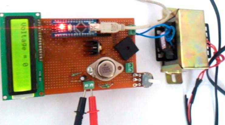
Batteries are generally used to power up the Electronic Circuit and Projects, as they are easily available and can be connected easily. But they drained off quickly and then we need new batteries, also these batteries cannot provide high current to drive a powerful motor. So to solve these problems, today we are designing our own Variable Power Supply which will provide Regulated DC voltage ranging from 0 to 24v with a maximum current up to 3 Amps.
For most of our Sensors and Motors we use voltage levels like 3.3V, 5V or 12V. But while the sensors requires current in milliamps, motors like servo motors or PMDC motors, which run on 12V or more, require a high current. So we are building here the Regulated Power Supply of 3A current with the Variable voltage between 0 to 24v. However in practical we got up to 22.2v of output.
Here the voltage level is controlled with help of a Potentiometer and voltage value is displayed on Liquid Crystal Display (LCD) which will be driven by an Arduino Nano. Also check out our previous Power supply circuits:
- 12v Battery Charger Circuit using LM317
- Variable Power Supply By Arduino Uno
- Cell Phone Charger Circuit
Materials Required:
- Transformer - 24V 3A
- Dot board
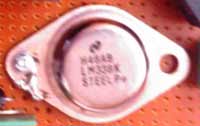
- LM338K High Current Voltage Regulator
- Diode Bridge 10A
- Arduino Nano
- LCD 16*2
- Resistor 1k and 220 ohms
- Capacitor 0.1uF and 0.001uF
- 7812 Voltage Regulator
- 5K variable Pot (Radio Pot)
- Berg stick (Female)
- Terminal Block
How it works:
A Regulated Power Supply (RPS) is one which converts your AC mains into DC and regulates it to our required voltage level. Our RPS uses a 24V 3A step down transformer which is rectified into DC using a diode bridge. This DC voltage is regulated to our required level by using LM338K and controlled by using a Potentiometer. The Arduino and LCD are powered by a low current rating Voltage regulator IC like 7812. I will explain the circuit step by step as we go through our project.
Connecting LCD with Arduino to Display Voltage Level:
Let’s start with the LCD display. If you are familiar with LCD interfacing with Arduino, you can skip this part and directly jump to next section and if you are new to Arduino and LCD, it won't be a problem as I will guide you with codes and connections. Arduino is an ATMEL powered microcontroller kit which will help you in building projects easily. There are lots of variants available but we are using Arduino Nano since it is compact and easy to use on a dot board
Many people have faced issues in interfacing a LCD with Arduino, thats why we try this first so that it does not ruin our project in last minute. I have used the following to start with:
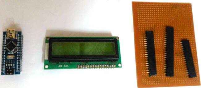
This Dot board will be used for our entire circuitry, it is recommended to use a female berg stick to fix the Arduino Nano so that it could be reused later. You can also verify the working using a breadboard (Recommended for beginners) before we proceed with our Dot board. There is a nice guide by AdaFruit for LCD, you can check it. The schematics for Arduino and LCD is given below. Arduino UNO is used here for schematics, but not to worry the Arduino NANO and UNO have the same pinouts and work the same.
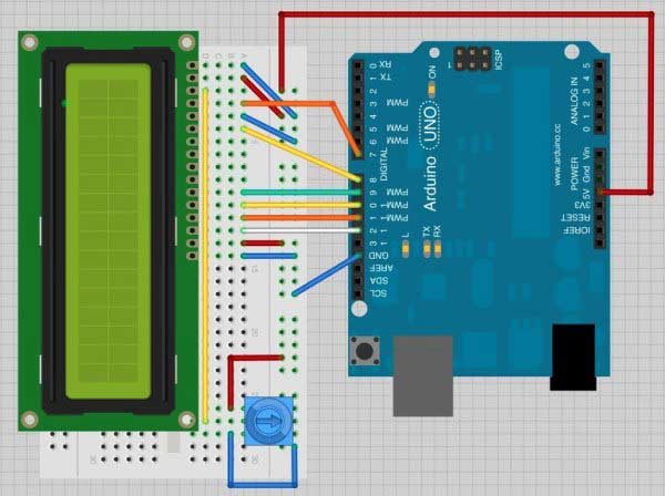
Once the connection the done you can upload below code directly to check the LCD working. The header file for LCD is given by Arduino by default, do not use any explicit headers as they tend to give errors.
#include <LiquidCrystal.h>
// initialize the library with the numbers of the interface pins
LiquidCrystal lcd(7, 8, 9, 10, 11, 12);
int a =5;
void setup() {
  // set up the LCD's number of columns and rows:
  lcd.begin(16, 2);
  // Print a message to the LCD.
  lcd.print("hello, world!");
}
void loop() {
  // set the cursor to column 0, line 1
  // (note: line 1 is the second row, since counting begins with 0):
  lcd.setCursor(0, 1);
  // print the number of seconds since reset:
  lcd.print(a);
}
This should get your LCD to work, but if you still face issues try the following:
1. Check you pins definition in the program.
2. Directly ground the 3rd pin (VEE) and 5th pin (RW) of your LCD.
3. Make sure you LCD pins are placed in the right order, some LCD's have their pins is another direction.
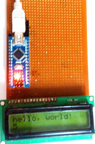
Once the program works it should look something like this. If you have any problems let us know by comments. I have used the mini USB cable to power the Arduino for now, but later we will power it using a voltage regulator. I soldered them to the dot board like this
Our aim is to make this RPS easy to use and also keep the cost as low as possible, hence I have assembled it on a dot board, but if you can offered a Printed circuit board (PCB) it will be great since we are dealing with high currents.
Building 0-24v 3A Variable Power Supply Circuit:
Now that our Display is ready let us start with the other circuits. From now it is advisable to proceed with extra caution since we are dealing directly with AC mains and high current. Check for continuity using a multimeter every time before you power you circuit.
The transformer we use is a 24V 3A transformer, this will step down our voltage (220V in India) to 24V, and we directly give this to our bridge rectifier. The bridge rectifier should will give you (root 2 times the input voltage) 33.9V, but don't be surprised if you get around 27 - 30 Volts. This is because of the Voltage drop across each diode in our bridge rectifier. Once we reach this stage we will solder it to our dot board and verify our output and use a terminal block so that we use it as a non regulated constant source if required.
Now let us control the output voltage by using a high current regulator like LM338K, this will be mostly available in metal body package, since it has to source high current. The schematics for variable voltage regulator are shown below.
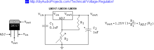
The value of R1 and R2 has to be calculated using the above formulae to determine the output voltage. You can also calculate the resistor values using this LM317 resistor calculator. In our case we get R1 to be 110 ohms and R2 as 5K (POT).
Once our Regulated output is ready we just have to power up Arduino, to do this we will use a 7812 IC since the Arduino will only consume less current. The input Voltage of 7812 is our rectified 24v DC output from rectifier. The output of regulated 12V DC is given to the Vin pin of Arduino Nano. Do not use 7805 since the maximum input voltage of 7805 is only 24V whereas 7812 can withstand upto 24V. Also a heat sink is required for 7812 since the differential voltage is very high.
The complete circuit of this Variable Power Supply is shown below,

Follow the Schematics and solder you components accordingly. As shown in schematics the variable voltage of 1.5 to 24V is mapped to 0-4.5V by using potential divider circuit, since our Arduino can only read voltages from 0-5. This variable voltage is connected to pin A0 using which the output voltage of the RPS is measured. The final Code for the Arduino Nano is given below in Code Section. Also check the Demonstration Video at the end.
Once the soldering work is done and the code is uploaded to Arduino, our Regulated Power Supply is ready to use. We can use any load which works from 1.5 to 22V with a current rating of maximum 3A.
Point to be kept in mind:
1. Be careful while soldering the connections any mismatch or carelessness will easily fry your components.
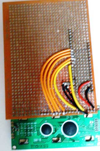
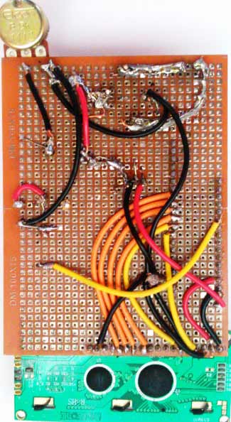
2. Ordinary solders might not be able to withstand 3A, this will lead eventually melt your solder and cause short circuit. Use thick copper wires or use more lead while connecting the high current tracks as shown in the picture.
3. Any short circuit or weak soldering will easily burn your transformer windings; hence check for continuity before powering up the circuit. For additional safety a MCB or fuse on Input side can be used.
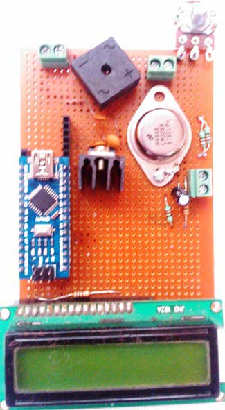
4. High current voltage regulators mostly come in metal can packages, while using them on dot board do not place components close to them as their body acts as the output of the rectified Voltage, further will result in ripples.
Also do not solder the wire to the metal can, instead use a small screw as shown in the picture given below. Solders don't stick to its body, and heating results in damaging the Regulator permanently.
5. Do not skip any filter capacitors from the schematics, this will damage you Arduino.
6. Do not overload the transformer more than 3A, stop when you hear a hissing noise from the transformer. It is good to operate between the ranges of 0 - 2.5A.
7. Verify the output of your 7812 before you connect it to your Arduino, check for overheating during first trial. If heating occurs it means your Arduino is consuming more current, reduce the backlight of the LCD to solve this.

Upgrade:
The Regulated Power Supply (RPS) that is posted above have few problem with the accuracy due to the noise present in the output signal. This type of noise is common in cases where an ADC is used, a simple solution to it is to use a low pass filter like RC filter. Since our circuited Dot board has both AC and DC in its trails, the noise will be high than that of other circuits. Hence a value of R=5.2K and C=100uf is used to filter out the noise in our signal.
Also a current sensor ACS712 is added to our circuit to measure the output current of the RPS. The below schismatic shows how to connect the Sensor to the to Arduino Board.

The new video shows how the accuracy has improved: https://www.youtube.com/watch?v=Uj1hHchvF7Q
Complete Project Code
#include <LiquidCrystal.h>
// initialize the library with the numbers of the interface pins
LiquidCrystal lcd(7, 8, 9, 10, 11, 12);
void setup()
{
  Serial.begin(9600);
  // set up the LCD's number of columns and rows:
  lcd.begin(16, 2);
  // Print a message to the LCD.
  lcd.setCursor(0, 0);
  lcd.print("RPS");
  lcd.setCursor(0, 1);
  lcd.print("-Circuit Digest");
  delay(2000);
  lcd.clear();
  lcd.setCursor(0, 0);
  lcd.print("Voltage = ");
}
int voltage;
void loop()
{
  int A1 = analogRead(A0);
  voltage = map(A1,0,1024,0,22);
  Serial.println(voltage);
  lcd.setCursor(10,0);
  lcd.print(voltage);
  delay(1000);
}
Comments
What if I want like 32 v and 3 amps of current. Can I modify something in this circuit?
The Lm317 has a differential voltage of 40V. This means for a variable power supply of (0-32) Volts the max differential voltage will be 45.2 (32*root 2).
Hence a single LM317 will not be able to bear it. This can be done by using two LM317 in parallel thus sharing the Dif Volatge.
What if I want to make a circuit without LCD display and with a fix output of 5v and 3A?
Thanks in Advance!
Hi Niobium,
The arduino and the LCD was used just to just display the output voltage, you can ignore it and proceed with the rest of the circuit and YES, it will work even then.
The maximum power rating of the circuit is 3A, you can load any device with 3A without any problems, but if you want to limit the current, this circuit is of no use. You can move to SMPS circuits or if you like to make it simple you can add a current limit (Protection) circuit to this.
But, I would recommend an SMPS for your project.
I am unable to measure the current in the circuit..how can I do the same..also I want to divide the output current at two different values..please suggest an idea..
Hi Ritu,
Which sensor are you using to measure the current ?
The problem might be with your code or the current senor, trying powering the sensor and measure the output voltage. It should be 2.5V. Now connect some load and check if the voltage changes it can either increase or decrease based on the direction of the current.
If you have any problem please explain them in detail.
I love this site....explained very well.... nicely explained....thank u...sir....great electronics project site that I have ever seen....
Thanks Niraj
hi Aswinth,
I am from kerala. Could you help me with Arduino to complete my project? It is a bit urgent. So please respond as early as possible so that we can work something out.
Regards,
Vineeth
Please! Help me please to have schematic and block diagram for single slot battery charger 4Amphere. Thank You
B.Aswinth Raj
Could you help me design a power supply with input 220VAC and output 0-100VDC (variable), 0-15A (variable) control by microprocessor?
I only change transformer to fit my project like your project, right?
No your project will require major remodification. Because the current rating is very high. 15A is really a high power and hence you cannot use this circuit for your project. You should use SMPS ciruits or commonly called as switching circuits
The circuit shown seems incorrect. C3 and pin 2 of J2 should be connected to ground (or the negative rail). In the schematic C3, J2 and the rest are connected over a short between U1 pin 3 and R1. No current will flow passed that short.
Yes JB you are correct. The circuit diagram is has a subtle mistake. The short wire should be remove and instead grounded. Would make the change as soon as possible
Can you please recheck circuit diagram I am to having problems getting it to work.
The arduino and the LCD was used just to just display the output voltage only, can you modify the circuit as well as the program for displaying the current also

You are are doing a good job thank you.