LED interfacing is the first thing, one would try to do while getting started with any microcontroller. So here in this tutorial we are going to interface a LED with 8051 microcontroller, and will write a C Program to blink the LED. We have used a very popular microcontroller AT89S52, of 8051 family, by ATMEL.
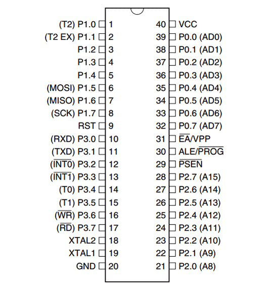
Before going into detail, we should get some brief idea about microcontroller AT89S52. It is 40 pin microcontroller, and has 4 ports (P0,P1,P2,P3), each port have 8 pins. We can consider each port as 8 bit register, from the software point of view. Each pin having one Input/output line, means every pin can be used for input as well as for output, i.e. to read data form some device like sensor or to provide its output to some output device. Some pins have the Dual functionality, which has been mentioned in bracket in Pin Diagram below. Dual functionally like for interrupt, counters, timers etc.

AT89S52 has two types of memory, first is RAM which has 256 Bytes of memory and second is EEPROM (Electronically Erasable and Programmable Read Only Memory) which has 8k bytes of memory. RAM is used to store the data during execution of a program and EEPROM used to store the Program itself. EEPROM is the flash memory which we used to burn the program into.
Circuit Diagram and Explanation
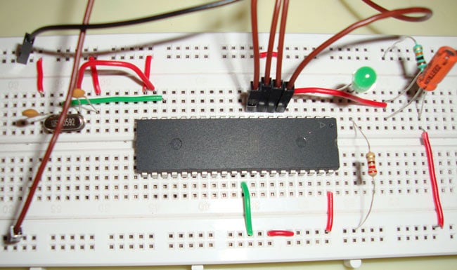
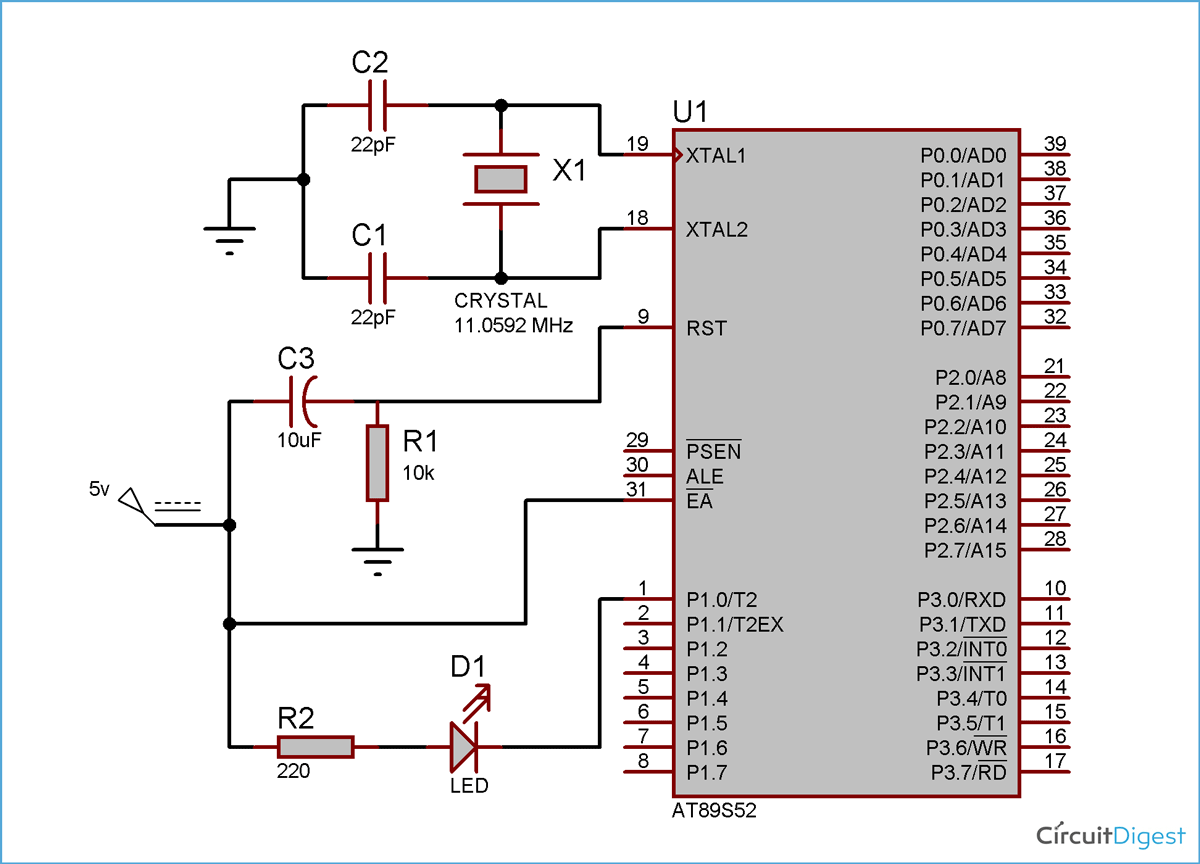
We are using pin one of port 1 to connect the LED. In embedded C programming we can access the PIN 1 of port 1 by using P1_0. We have connected a crystal oscillator of 11.0592MHz frequency to the PIN 19 and 18 i.e. XTAL1 and XTAL2. Crystal oscillator is used to generate clock pulses, and clock pulse is used to provide the mean for timing calculation, which is mandatory to synchronise all the events. These type of crystals used in almost every modern digital equipment like in computers, watches etc. Most commonly used Crystal is quartz. It's a resonant oscillator circuit and capacitors are used to oscillate the crystal, so we have connected here 22pf capacitors. You can read about “resonant circuits” to know more.
The circuit diagram for LED interfacing with 8051 microcontroller 89S52 is shown in above figure. Pin 31 (EA) is connected to Vcc, which is an active low pin. This should be connected to Vcc when we are not using the any external memory. Pin 30(ALE) and pin 29 (PSEN) are used to connect microcontroller to the external memory and Pin 31 tells microcontroller to use external memory, when connected to Ground. We are not using any external memory so we connected Pin31 to Vcc.
Pin 9 (RST) is the reset PIN, used to reset the microcontroller and program again starts from the beginning. It resets the microcontroller when connected to HIGH. We have used standard reset circuitry, 10k ohm resistor and 1uF Capacitor to connect the RST pin.
Now the interesting part here is that we connect the LED in reverse, means negative leg with microcontroller PIN, because microcontroller don’t provide enough power to glow an LED, so here the LED run on the negative logic like when, pin P1_0 is 1 then LED will be tuned OFF and when pin output is 0 then LED will be turned ON. When PIN output is 0, it behaves like ground and LED glows.
Code Explanation
Header REGX52.h has been included to include the basic register definitions. There are many types of variables and constants in embedded C like int, char, unsigned int, float etc, you can learn them easily. Here we are using unsigned int whose range is from 0 to 65535. We are using “for loop” for creating delay, so that LED will be ON for some time (P1_0=0, negative LED logic) and and OFF (P1_0=1, negative LED logic) for delayed time. Generally when “for loop” runs for 1275 times it, gives delay of 1ms, so we have created ‘delay’ function for creating DELAY and called it from main program (main()). We can pass DELAY time (in ms) while calling “delay” function from main function. In program, “While(1)” means that program will execute infinitely.
I am briefly explaining, how 1275 times run of “for” loop give delay of 1ms:
In 8051, 1 machine cycle requires 12 crystal pulses to execute and we have use 11.0592Mhz crystal.
So time required for 1 machine cycle: 12/11.0592 = 1.085us
So 1275*1.085=1.3ms, 1275 times of “for” loop gives nearly 1ms of delay.
The exact time delay produce by “C” program is very difficult to compute, when measuring from oscilloscope (CRO), for (j=0;j<1275;j++) give delay of nearly 1ms.
So we can understand by simply interfacing LED with 8051 microcontroller, that with a simple coding that, we can interact and control the hardware through software (programming) using microcontroller. Also we can manipulate each port and pin of microcontroller through programming.
Complete Project Code
#include <REGX52.h>
delay(unsigned int y){
    unsigned int i,j;
for(i=0;i<y;i++){
    for(j=0;j<1275;j++){}
}
}
main(){
    while(1){
        delay(100);
        P1_0 = 0;
        delay(100);
        P1_0 = 1;
    }
}
Comments
You must check this Tutorial
You must check this Tutorial : Getting Started with 8051 Microcontroller
jayanth
jayanth
i followed your exact circuit and my code is correct when i tried to debug i could see it is working fine. do i need to pull out reset pin to make my led glow?
i feel like there is a small step i m missing out...
can you please elaborate your explanation after I arranged circuit and given power supply ....
then do my led glow directly or after dumping hex file? or after dumping hex file do i need to pull out reset pin?
Thanks
Vijay
Led should glow just after
Led should glow just after the dumping of HEX file, try adding a Reset button like here 7 Segment Display Interfacing with 8051 Microcontroller , and press the reset button couple of times.
error report
I' m compiling the program for AT89S52 microcontrller. when I do build target than generate the "return value". where i do write return value ?
what is the output voltage of
what is the output voltage of the At89s52 when using a 5v power supply
Will the circuit works if I
Will the circuit works if I do not use reset circuit?
Programming using MCP2221
I soldered the RX and TX Pins (UART) of the AT89S52 to a MCP2221. Now I want to programm the microcontroller, what things do I need?


Hi
I am new to this embedded programming hope you will help me...
i am using progisp s.w to flash into MC, there i found out connection pins are different from yours as you are using 8051 loader s.w and i connected as per your directions but i m getting an error "chip enable program error". what i feel is circuit pins of hardware kit may be different and differs from s.w to s.w.
please let me know where i m doing wrong.
thanks
vijay