

To verify product functionalities and design parameters, a power supply circuit requires sophisticated testing methods and electronic test equipment. It is necessary to gather better knowledge about the SMPS testing requirements to fulfill product standards. In this article, we will learn how to test SMPS circuit and talk about some of the most basic tests for SMPS and the safety norms that need to be followed to test an SMPS circuit easily and efficiently. The following examination gives you an idea about the most basic power supply architectures and their testing process.
If you are an SMPS Design Engineer, you can also check out the article on SMPS PCB Design Tips and SMPS EMI Reduction Techniques both of which we discussed earlier.
Basics of SMPS Testing – Points to Remember
Switched-mode power supplies (SMPS) circuits normally switch very high voltage DC with an auto adjustable duty cycle, in order to regulate the output power with high efficiency. But doing so introduces safety concerns that can be harmful to the device if not taken care of.
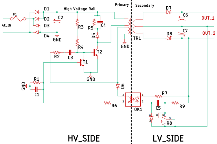
The above schematic shows a line-powered power supply which utilizes the flyback topology to convert high voltage DC to low voltage DC. The schematic was made to understand the high voltage side and low voltage side clearly. In the high voltage side, we have a fuse as a protection device, then the mains voltage is rectified and filtered by the input rectifier diodes D1, D2, D3, D4, and capacitor C2, this means the voltage level in between those lines can reach more 350V or more at a given point in time. Engineers and technicians should be very careful while working with these potentially lethal voltage levels.
Another thing to be very cautious about is the filter capacitor C2, as it holds the charge for a long time, even when the power supply is disconnected from the mains. Before we proceed with any testing of the SMPS circuit, this capacitor needs to be discharged properly.
The switching transistor T2 is the main switching transistor, and T1 is the auxiliary switching transistor. As the main switching transistor is responsible for driving the main transformer, it is most likely to get very hot, and as it comes with a TO-220 package there's a chance that the hit sink will have high voltage on it. The test operator has to be extra careful in this section. One of the most important parameters to take note of is the transformer section. In the schematic, it is denoted as T1, the transformer T1 in conjunction with the optocoupler OK1 provides isolation from the primary side. In a test situation where the secondary section is connected to earth ground and the primary section is floating. The situation connecting a test instrument in the primary section will cause a short circuit to the ground, which can permanently damage the test instrument. Other than that, a typical flyback converter needs a minimum load to work properly otherwise the output voltage cannot be regulated properly.
Power Supply Tests
Power supplies are used in a variety of products. As a result, the test performance needs to be different depending on the application. For example, the test setup in a design lab is done to verify design parameters. These tests require high-performance test equipment with a proper control environment. In contrast, power supply testing in production environments primarily focuses on overall function based on the specifications determined during the product design phase.
Load Transient Recovery Time:
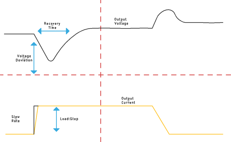
The constant-voltage power supply has a built-in feedback loop that continuously monitors and stabilizes the output voltage by changing the duty cycle accordingly. If the delay between the feedback and control circuit approaches a critical value at its unity-gain crossover, the power supply gets unstable and starts oscillating. This time delay is measured as an angular difference, and it is defined as the degree of phase shift. In a typical power supply, this value is 180 degrees of phase shift between the input and output.
Load Regulation Test:
Load regulation is a static parameter in which we test the output limit of the power supply for a sudden change in load current. In a constant voltage power supply, the test parameter is the constant current. While in constant current power supply it is the constant voltage. By testing these parameters, we can determine the ability of the power supply to withstand the rapid changes in the load.
Current Limit Test:
In a typical current limited power supply, the test is performed to observe the current limiting capabilities of a constant voltage power supply. The actual current limit can be fixed or it can be variable depending on the type and requirement of the power supply.
Test for Ripple and Noise:
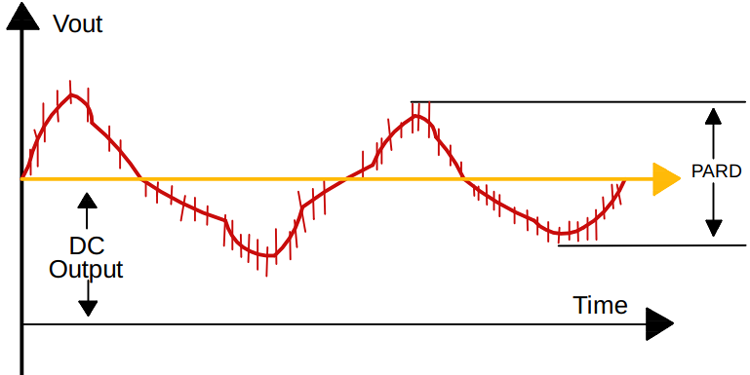
A typically good quality power supply or many audio grade high-quality power supplies are tested to measure their output ripple and noise. The most common name of this test is known as PARD (Periodic and Random Deviation). In this test, we measure the periodic and random deviation of the output voltage over limited bandwidth along with other parameters like input voltage, input current, switching frequency, and load current constantly. In simpler terms, we can say with the help of this process, we measure the underside AC coupled noise and ripple after the output rectification and filtering stage.
Efficiency Test:
The efficiency of a power supply is simply the ratio between its total output power divided by its total input power. The output power is DC where the input power is AC, so we need to obtain a true RMS value of the input power to achieve this. A good quality wattmeter with true RMS capabilities can be used, by doing this test, the tester can understand the overall design parameters of a power supply if the measured efficiency is out of space for a chosen topology, then it's a clear indication of a poorly designed power supply or defective parts issue.
Start-Up Delay Test:
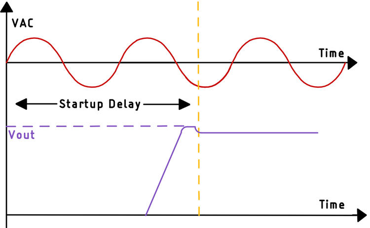
The start-up delay of a power supply is the measurement of the time taken to get the output of the power supply stable. For a switching power supply, this time is very crucial for the proper sequencing of the output voltage. This parameter also plays an important role when it comes to powering sensitive electronic equipment and sensors. If this parameter is not properly handled, it leads to the formation of spikes which can destroy the switching transistors or even the connected output load. This problem can be easily solved by adding a “soft start” circuit to limit the initial current for the switching transistor.
Overvoltage Shutdown:
A typically good power supply is designed to shut down if the output voltage of the power supply exceeds a certain threshold level, if not, this can be harmful to the device on load.
Typical SMPS Testing Setup
With all the required parameters cleared up, we can finally move on to testing the SMPS circuit, a good SMPS testing bench should have commonly available testing and safety equipment that minimizes safety concerns.
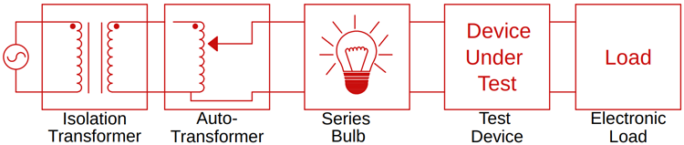
The Isolation Transformer:
The isolation transformer is there to electrically isolate the primary section of the SMPS circuit. When isolated, we can directly attach any ground probe, negating the high voltage side of the power supply. This eliminates the possibility of a short circuit direct to the ground.
The Auto-Transformer:
The autotransformer can be used to slowly increase the input voltage of an SMPS circuit, doing so while monitoring the current can prevent a catastrophic failure. In a different situation, it can be used to simulate low voltage and high voltage situations, doing so we can simulate situations where line voltage changes abruptly, this will help us understand the behavior of the SMPS in those conditions. In general, a universal rated power supply ranges from 85V to 240V can be tested with the help of an autotransformer, we can test the output characteristic of an SMPS circuit very easily.
The Series Bulb:
A light bulb in series is a good practice when it comes to testing an SMPS circuit, a certain failure of a component can lead to exploding MOSFETs. If you are thinking about an exploding MOSFET, you read that right! MOSFET does explode in high current power supplies. So, an incandescent light bulb in series can prevent a MOSFET from getting blasted.
The Electronic Load:
To test the performance of any SMPS circuit, a load is necessary, while some high-power resistor is most certainly the easy way to test certain load capacity. But it's almost impossible to test the output filter section without a varying load, that is why an electronic load becomes necessary as we can easily measure output noise at different load conditions by varying the load linearly.
You can also build your own adjustable electronic load using Arduino which can be used for low power SMPS testing. With the help of an electronic load, we can easily measure the performance of the output filter, and it's necessary because a poorly designed output filter, in a certain load condition, can couple harmonic and noise at the output, which is very bad for sensitive electronics.
Testing the SMPS with a High Voltage Differential Probe
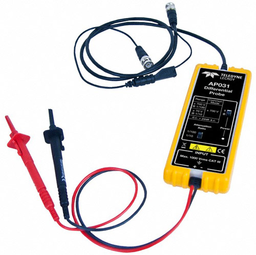
While voltage measurement can be done easily with the help of an isolation transformer but a better way is to use a differential probe for high-voltage measurements. Differential probes have two inputs and measure the difference in the voltage between the inputs. It does this by subtracting the voltage at one input from the other without any intervention from ground rails.
These types of probes have a high Common Mode Rejection Ratio (CMRR) which improves the dynamic range of the probe. In a generic SMPS circuit, the primary side switches with a very high switching voltage of 340V and a relatively fast transition time. Which in case generates noise, in these situations if we try to measure the input signal in the gate of the MOSFET, we will gate high noise rather than an input switching signal. This problem can easily be eliminated by using a high voltage differential probe with high CMRR which rejects the interfering signals.
Conclusion
Designing and testing an underdeveloped power supply can present safety concerns. However, as shown in the article common practice and testing equipment can certainly reduce the risk greatly.
Hope you enjoyed the article and learned something useful. If you have any questions, you can leave them in the comment section below or use our forums to post other technical questions.
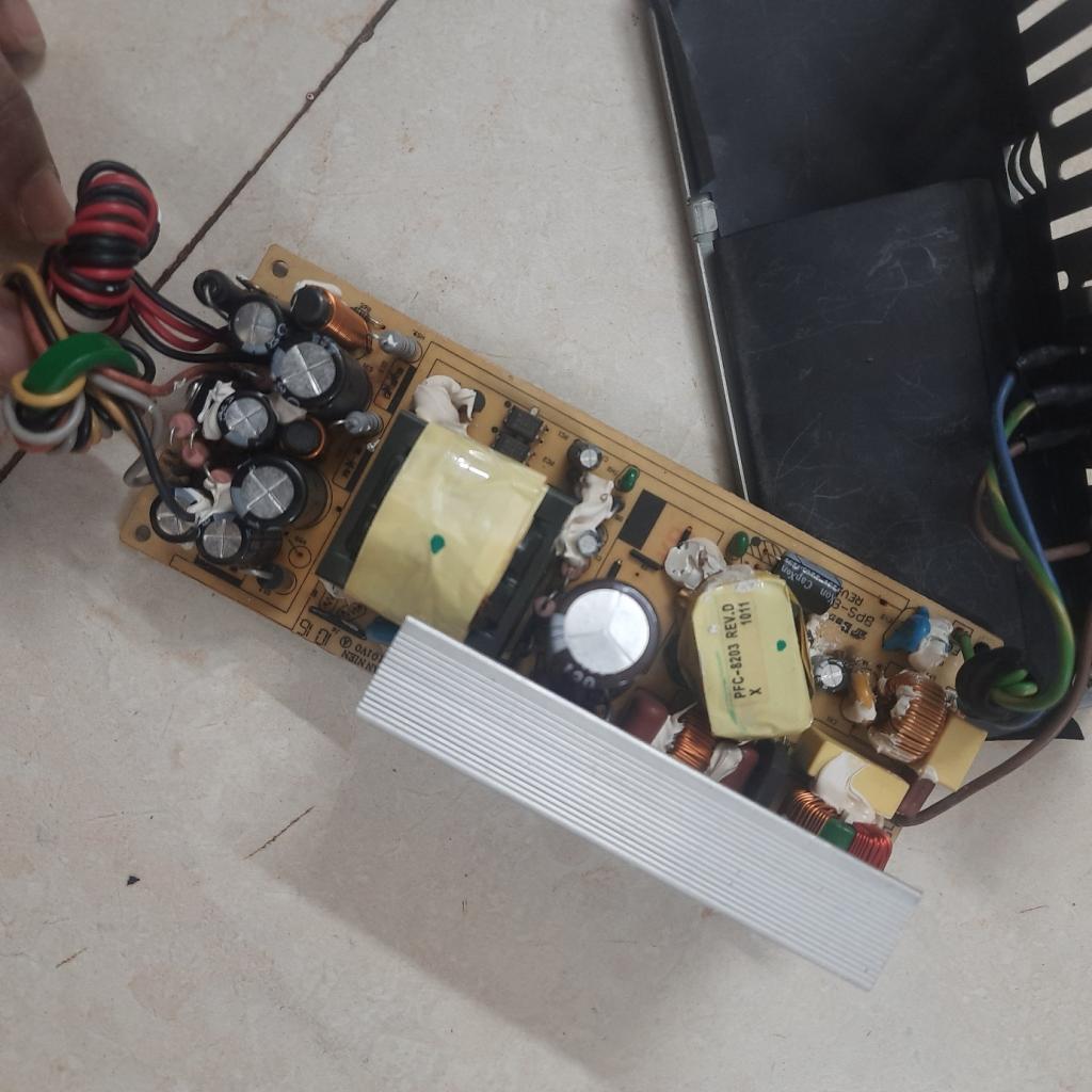
Can anyone tell how to repair above shown hp scanner smps model 8203 setp by step
