

A Soft Start Circuit prevents the sudden current flow in the circuit during the start. It slows down the rate of rising output voltage by minimizing the excess current flow during the start. It is useful to protect the devices or electronic components from the damage caused by instantaneous high input current. Some components which are current limited and having poor load regulation can get damaged because of this high input current. Here we are building the soft start circuit using a voltage regulator IC LM317 and a PNP transistor BC557.
Material Required
- LM317-Adjustable Voltage Regulator IC
- BC557-PNP Transistor
- Diode – 1N4007
- Resistor – (1k, 5.6k, 47k)
- Capacitor – (0.1uf, 22uf)
- Input Supply - 9V
- Breadboard
LM317 Voltage regulator IC
It’s an adjustable three-terminal voltage regulator IC, with a high output current value of 1.5A. The LM317 IC helps in current limiting, thermal overload protection and safe operating area protection. It can also provide float operation for High voltage application. If we disconnect the adjustable terminal still LM317 will helpful in Overload protection. It’s having a typical line and load regulation of 0.1%. This is also a Pb-free device.
Its operating and storage temperature is in range of -55 to 150 °C, and provide a maximum output current of 2.2A. We can provide input voltage in the range of 3v-40v DC and it can give output voltage of 1.25 v to 37v which we can vary according to the need, by using two external resistors on adjustable PIN of LM317. These two resistors works as voltage divider circuit used to increase or decrease the output voltage.
Pinout of LM317

Soft Start Circuit Diagram

Note: The input voltage should always be higher (atleast +3V) than the desired output voltage (LM317 max output is 37V).
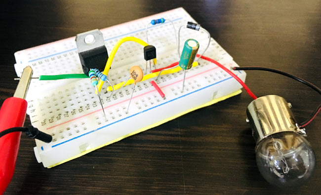
Here, we have connected a Bulb with soft start circuit to slowly glowing the bulb to its full brightness. You can vary the glowing rate of bulb by changing the value of the capacitor like to increase the rising time increase the value of capacitor C2.
Working of Soft Start Circuit
Here, we are using LM317, a linear and positive voltage regulator IC, which automatically reduce its output current whenever it’s in underload or in overheating condition.
The combination of the BC557 PNP transistor and the capacitor C2 helps the circuit to gradually increase the output voltage.
Initially, when the capacitor is not charged the output voltage of the circuit is defined as:
VC1 + VBE + 1.25V
= 0 + 0.7 + 1.25
= 1.95V
Where, VC1 is the voltage across capacitor, VBE is base to emitter voltage and 1.25 is the minimum output voltage of the LM317.
As the voltage across capacitor C2 increases, Vout rises at the same rate and reaches to the desired output voltage set according to the resistor’s value. Hence, as the output voltage reaches to the desired value the transistor turns off.
So, as we start the power supply, the bulb light starts getting brighter as per the voltage across it. So this circuit prevents the sudden rush of current into the circuit, hence prevents the device from getting damaged.
Advantages of Soft Start Circuit
- Used to reduce the inrush current and increase the durability of device.
- Improve Efficiency
- Soft Start Circuits are cheap and small in size
- Like motor soft starter are used for Pump motors and other industrial motors.
