
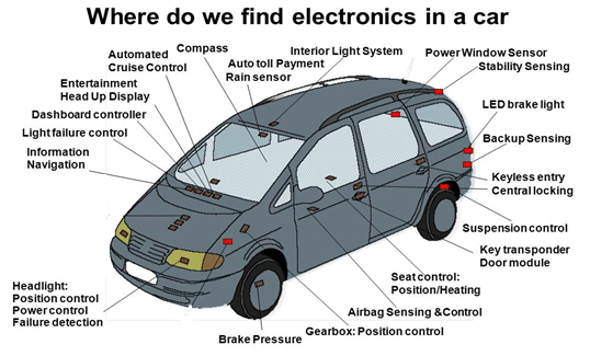
When current passes through a conductor it creates electromagnetic fields and almost all electronic devices like TVs, washing machines, induction stove, traffic lights, mobile phones, ATMs and laptops etc., will emit the electromagnetic fields. Fossil fueled vehicles also suffer from Electromagnetic Interference (EMI) - The ignition system, starter motor and switches cause broadband EMI and electronic devices cause narrowband EMI. But as compare to ICE (Internal Combustion Engine) vehicles, Electric Vehicles are combination of various subsystems and electronic components like battery, BMS, DC-DC converter, inverter, electric motor, high-power cables distributed around the vehicle and chargers, all these are working at high power and frequency levels which causes the emission of high-level low-frequency EMI.
If we observe the power and the voltage ratings of available electric vehicles, power ratings are between few tens of KW to hundreds of KW whereas voltage ratings are in hundreds of volts so that current levels will be in hundreds of Amperes, which causes stronger magnetic fields
- Nissan LEAF is having 125 kW rear wheel drive works on 400 VDC
- BMW i3 is having 125 kW rear wheel drive works on 500 VDC
- Tesla model S is having 235 kW Rear wheel drive works on 650 VDC
- Toyota Prius (3rd gen.) is having 74 kW Front wheel drive works on 400 VDC
- Toyota Prius PHV is having Front wheel drive rated 60 kW works on 350 VDC
- Chevrolet Volt PHV is having Front wheel drive rated 55 kW (x2) works on 400 VDC
Let consider an electric vehicle with 100KW electric drive operating at 400V means it is having current of 250A which creates a strong magnetic field. While designing the vehicle we have to assess EMC (Electromagnetic Compatibility) of all these subsystems and components to ensure components safety along with living beings safety.
Terms & Definitions related to EMC and EMI
EMC (Electromagnetic compatibility) of a device or equipment means it’s ability to not to be affected by electromagnetic field (EMF) and not to affect other systems operation with it’s EMF when it is operating in electromagnetic environment. EMC represents electromagnetic emission, susceptibility, Immunity and coupling issues.
Electromagnetic Emission means generation and releasing of electromagnetic energy into environment. Any unwanted emission causes interference or disturbance to other electronic device operation which is operating in the same environment i.e, known as Electromagnetic Interference (EMI).
Electromagnetic Susceptibility of a device indicates it’s vulnerability to unwanted emissions and interference which causes the malfunction or break down of device. If a device is more susceptible means it is less immune to electromagnetic interference.
Electromagnetic Immunity of a device means it’s ability to operate normally in the presence of electromagnetic environment without experiencing interference or break down due to the electromagnetic emissions from another electronic device.
Electromagnetic Coupling means mechanism of one device’s emitted electromagnetic field reaching or interfering with other device.
Sources of Electromagnetic Interference (EMI) in EV
")
- Power Converters are known to be the main source of electromagnetic interference within electric drive systems. These are having high speed switching device, e.g. conventional Insulated Gate Bipolar Transistors (IGBT) work at frequencies ranging from 2 to 20 kHz, fast IGBTs can work up to 50 kHz and SiC MOSFETs can even work frequencies above 150 KHz.
- Electric Motors which are operating at high power levels causes electromagnetic emissions and it act as path for EM noise through it's impedance. And this impedance changes as a function of frequency. As electric motor drives use power inverters with high-speed PWM switching operation, surge voltages are occurring at the motor terminals, which cause the radiated EM noise. And the shaft current may cause damage of motor bearings and malfunction of the vehicle controller.
- As traction batteries are distributed, the currents in the batteries and in the interconnectors become a significant source for EMF emission and these are main part of the path for EMI.
- Shielded and Unshielded Cables carrying high level current between various subsystems like battery to power converter, power converter to motor etc, in the EV causes stronger magnetic fields. As available space in EV for wiring harness is limited, high voltage and low voltage cables are placed near to each other causes electromagnetic interference between them.
- The battery chargers and the wireless charging facilities are the major external EMI sources apart from EV internal EMI source. When wireless power technology applied to charge the EV, a strong magnetic field in the range of several tens to hundreds of kilohertz produces to transfer several KWs to tens of KWs of power.
EMI impact on Electric Vehicle Electronic Components
Nowadays with the advancement in technology, automobiles contain more electronic components and systems for proper operation and reliability. If we see the electric vehicle architecture large amount of electrical and electronic systems placed into a confined space. This causes electromagnetic interference or cross talk between these systems. If EMC not maintained properly these systems may malfunction or even may fail to operate.
EMC Standards for Electric Vehicles
Most of the automotive EMC standards are set by the Society of Automotive Engineers (SAE), the International Standards Organization (ISO), the International Electrotechnical Committee (IEC), The Institute of Electrical and Electronics Engineers Standards Association (IEEE-SA), the European Community (EC) and the United Nations Economic Commission for Europe (UNECE).
ISO 11451 specifies the general conditions, guidelines and basic principles to test the vehicle to determine the immunity of ICE and electric vehicles over electrical disturbance narrowband radiated EMF.
ISO 11452 specifies the general conditions, guidelines and basic principles to test the component to determine the immunity of electronic components of ICE and electric vehicles over electrical disturbance narrowband radiated EMF.
CISPR12 specifies the limits and methods of measurement to test the radiated electromagnetic emissions from electric vehicles, ICE vehicles and boats.
CISPR25 specifies the limits and methods to measure the radio disturbance characteristics and the procedure to test the vehicle to determine the RI/ RE levels for the protection of receivers used on board vehicles.
SAE J551-1 specifies performance levels and Methods of measurement of EMC of vehicles and devices (60Hz-18GHz).
SAE J551-2 specifies test limits and methods of measurement of radio disturbance (emission) characteristics of vehicles, Motorboats, and spark-ignited Engine Driven Devices.
SAE J551-4 specifies test limits and methods of measurement of radio disturbance characteristics of vehicles and devices, broadband and narrowband, 150 KHz to 1000 MHz.
SAE J551-5 specifies performance levels and methods of measurement of magnetic and electric field strength from electric vehicles, 9 kHz to 30MHz.
SAE J551-11 specifies vehicle electromagnetic immunity-Off vehicle source.
SAE J551-13 specifies vehicle electromagnetic immunity-bulk current injection.
SAE J551-15 specifies vehicle electromagnetic immunity-electrostatic discharge which will be done in shielded room.
SAE J551-17 specifiesvehicle electromagnetic immunity-power line magnetic fields.
2004/144 EC - Annex IV specifies method of measurement of radiated broadband emissions from vehicles.
2004/144 EC - Annex V specifies method of measurement of radiated narrowband emissions from vehicles.
2004/144 EC - Annex VI specifies method of testing for immunity of vehicles to electromagnetic radiation.
AIS-004(Part 3) provides requirements for Electromagnetic Compatibility in Automotive Vehicles.
AIS-004(Part 3) Annex 2 explains method of measurement of radiated broadband electromagnetic emissions from vehicles.
AIS-004(Part 3) Annex 3 explains method of measurement of radiated narrowband electromagnetic emissions from vehicles.
AIS-004(Part 3) Annex 4 explains method of testing for immunity of vehicles to electromagnetic radiation.
AIS-004(Part 3) Annex 5 explains method of measurement of radiated broadband electromagnetic emissions from electrical/electronic sub assemblies.
AIS-004(Part 3) Annex 6 explains method of measurement of radiated narrowband electromagnetic emissions from electrical/electronic sub assemblies.
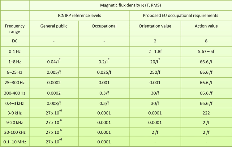
Limits to Exposure of Electromagnetic Fields to Humans
Electric vehicles produce non-ionizing electromagnetic radiations which don’t effect on human health for short time exposure. But for long time exposure if the radiated magnetic field is more than the standard limits, it effects human health. So, while designing electric vehicle the hazards with magnetic field exposure must be taken into account.
Electromagnetic exposure to passengers affects by different configurations, power levels and topologies of electric vehicle like front wheel drive or rear wheel drive, battery placement and the distance between power equipment to the passengers etc,.
By considering possible harmful effects of human exposure to electromagnetic fields international organizations, including the World Health Organization (WHO) and the International Commission for Non-ionizing Radiation Protection (ICNIRP), EU directives, IEEE have specified limits to maximum permissible magnetic field exposure to public.
|
Frequency (Hz) |
Magnetic fields H (AM-1) |
Magnetic flux density B(T) |
|
< 0.153 Hz |
9.39 x 10⁴ |
118 x 10-3 |
|
0.153 -20Hz |
1.44 x 10⁴/f |
18.1 x 10⁻³/f |
|
20- 759 Hz |
719 |
0.904 x 10⁻³ |
|
759 Hz - 3KHz |
5.47 x 10⁵/f |
687 x 10-3/f |
Below is the table showing the Maximum permissible magnetic field levels to general public as per IEEE standard
Occupational means people who are exposed to EMF while doing their regular job activities.
General public means the rest of public other than occupational exposed to electromagnetic fields
Orientation values have no adverse health effect under normal working conditions and for persons not having any active Implanted Medical Device or being pregnant. These are corresponds to field strength.
Action value causes some effects exposed to these levels. These are corresponds to the maximum directly measurable field.
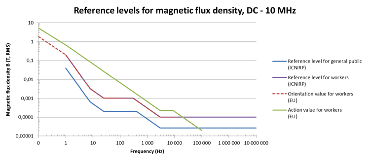
- Basically Action value is higher than Orientation value.
- Occupational public exposure values are higher than those for the general public exposure level.
Electromagnetic Compatibility Tests
EMC Testing need to be done to check whether electric vehicle follows the required standards or not. Laboratory tests and road tests are performed on electric vehicle to assess EMC. These tests consists emissions, susceptibility and immunity tests.
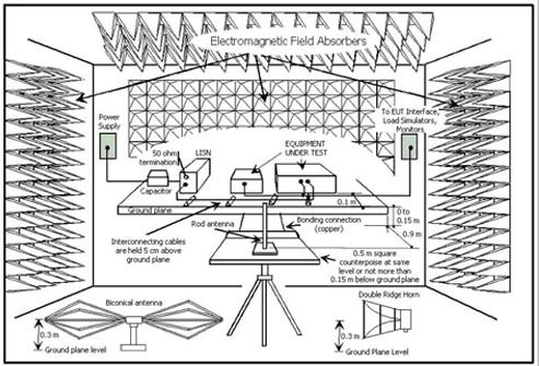
Laboratory tests are done to characterize the magnetic field emissions and susceptibility from all of the on-board electrical equipment in an EMC test chamber. These chambers are anechoic and reverberation types.
For conducted emission testing, transducers include the line impedance stabilization network (LISN) or artificial mains network (AMN) is used. For radiated emission testing, antennas are used as transducers. Radiated emissions are measured in all directions around the device under test (DUT).
Susceptibility testing uses high-powered source of RF EM energy and a radiating antenna to direct the electromagnetic energy to the DUT. While doing test on electric vehicle except the device under test (DUT) everything will be switched off and then the magnetic field will be measured.
Outside tests are done in a real-world on road driving conditions. In these tests the vehicle under test need to drive with maximum acceleration and deceleration to ensure maximum current during traction and regenerative braking. These tests will be performed on straight road where the magnetic fields due to earth is constant and in some cases on steep slope roads. While doing on road tests we have to identify the external magnetic perturbations from external sources like railway lines, manhole covers and other cars, power distribution equipments, high-voltage transmission lines and power transformers.
Design guidelines for better EMC and to lower the EMI
- DC cables carrying high currents should be made in twisted form so that the current in this cable flow in opposite direction results in minimization of EMF emission.
- Three phase AC cables should be twisted and need to place as close as possible to minimize EMF emission from them.
- And all these power cables need to place as far away as possible from passenger seat region. And these connections should not form a loop.
- If the distance between passenger seats and cable is less than 200 mm, shielding must be adopted.
- Motors need to be placed farther away from passenger seat area and the rotation axis of motor should not point towards passenger seat area.
- As steel has better shielding effect, if weight permits instead of aluminium, steel metal housing need to be used for motor.
- If the distance between the motor and passenger seat area is less than 500mm, shielding like steel plate need to be employed between the motor and passenger seat area.
- Motor housing should be grounded to chassis properly to minimize any electrical potential.
- To minimize the cable length between the inverter and motor they mounted as close as possible to each other.
- To suppress the surge voltage, shaft current and radiated noise an EMI noise controller should be attached to the motor terminals.
- A digital active EMI filter needs to be integrated into the digital controller of a DC-DC converter to charge the low voltage battery and to provide significant EMI attenuation.
- To suppress the EMI during wireless charging, resonant reactive shielding has been developed. Here the leakage magnetic field passes through the resonant reactive shield coils in such a way that the induced EMF in each shield coil can cancel the incident EMF and the magnetic field leakage can be effectively suppressed without consuming additional power.
- Conductive shielding, magnetic shielding and active shielding technologies have been developed to shield the electromagnetic field emission from the WPT system.
- An EMI noise controller has been developed for electric vehicles, which is attached on the motor terminals to suppress the surge voltage, shaft current and radiated noise.
