

The term MEMS stands for Micro-Electro-Mechanical Systems, now that we know what the full form of MEMS is lets try and understand what it is. MEMS is a combination of micrometer-sized devices composed of both electronic components and mechanical moving parts. These are miniature machines on a microscopic scale, meaning the physical dimensions of a MEMS can be anywhere from one micrometer to several millimeters. With the help of MEMS Technology, we can build very tiny and fully functional mechanical structures that are relatively simple with no moving elements, or extremely complex electromechanical systems.
Overview of MEMS Technology
MEMS Technology includes various microfabrication techniques used to manufacture MEMS devices. The MEMS technology was first introduced in the 1965’s but mass production has not started till 1980. There are over 100 billion or more MEMS devices currently active in various applications, and they can be seen in mobile phones, laptops, GPS systems, automobiles, etc.
MEMS technology is incorporated in many electronic components and their number is growing daily. With the advancement in developing cheaper MEMS devices, we can see them taking over many more applications in the future.
MEMS Devices and Sensors
As MEMS devices perform better than normal devices unless a better-performing technology comes into play MEMS will stay on the throne. In MEMS technology most notable elements are micro sensors and micro actuators which are appropriately categorized as transducers. These transducers convert energy from one form to another. In the case of microsensors, the device typically converts a measured mechanical signal into an electrical signal and a microactuator converts an electrical signal into mechanical output.
A few typical sensors based on MEMS technology are explained below.
- Accelerometers
- Pressure sensors
- Microphone
- Magnetometer
- Gyroscope
MEMS Accelerometers
Before going into design let us discuss the working principle used in designing MEMS accelerometers and for that consider a mass-spring set up shown below.
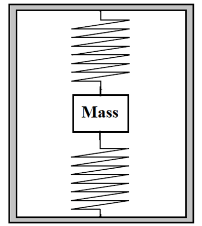
Here a mass is suspended with two springs in a closed space and the setup is considered to be at rest. Now if the body suddenly starts moving forward then the mass suspended in the body experiences a backward force which causes a displacement in its position. And because of this displacement springs get deformed as shown below.
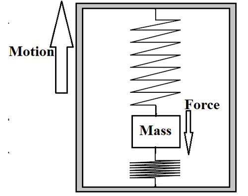
This phenomenon also must be experienced by us when sitting in any moving vehicle like car, bus, and train, etc. so the same phenomenon is used in designing the accelerometers.
Now consider a similar scenario but instead of mass, we will use conductive plates as a moving part attached to the springs. The entire setup will be as shown below.
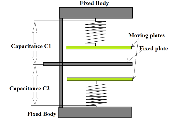
In the diagram, we will consider the capacitance between the top moving plate and a fixed plate:
C1= e0A / d1
where d1 is the distance between them.
Here we can see that capacitance C1 value is inversely proportional to the distance between top moving the plate and fixed plate.
The capacitance between the bottom moving plate and fixed plate
C2= e0A / d2
where d2 is the distance between them
Here we can see that capacitance C2 value is inversely proportional to the distance between the bottom moving plate and fixed plate.
When the body is at rest both the top and bottom plates will be at equal distance from the fixed plate so capacitance C1 will be equal to capacitance C2. But if the body suddenly moves forward then the plates get displaced as shown below.
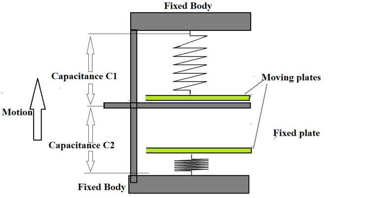
At this time the capacitance C1 gets increased as the distance between the top plate and fixed plate decreases. On the other hand capacitance, C2 gets decreases as the distance between the bottom plate and fixed plate increased. This increase and decrease in capacitance is linearly proportional to the acceleration on the main body so higher the acceleration higher the change and lower the acceleration lesser the change. Here is a simple animation showing the working of MEMS accelerometer, you can see how the capacitance changes (yellow lines) based on the force exerted on the spring (blue lines).
This varying capacitance can be connected to an R-C oscillator or another circuit to get the appropriate current or voltage reading. After getting the desired voltage or current value we can use that data for further analysis easily.
Although this setup can be used for measuring the acceleration successfully it is bulky and not practical. But if we use MEMS technology we can shrink the entire setup to a size of few micrometers making the device more applicable.
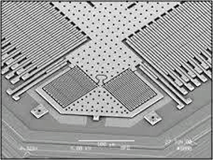
In the above figure, you can see the actual setup used in a MEMS accelerometer. Here the multiple capacitor plates are organized both in a horizontal and vertical direction to measure acceleration in both directions. The capacitor plate is sized to a few micrometers and the entire setup will size up to few millimeters, so we can use this MEMS accelerometer in battery-operated portable devices like smartphones easily.
MEMS Gyroscope

MEMS gyroscope is very popular and is used in many applications. For example, we can find MEMS gyroscope in airplanes, GPS systems, smartphones, etc. MEMS gyroscope is designed based on the Coriolis Effect. For understanding the principle and working of MEMS gyroscope, let us look into its internal structure.
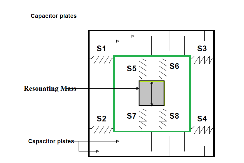
Here S1, S2, S3&S4 are the springs used for connecting the outer loop and second loop. While S5, S6, S7&S8 are springs used for connecting the second loop and mass ‘M’. This mass will be resonating along the y-axis as shown by the directions in the figure. Also, this resonation effect is usually achieved by using the electrostatic force of attraction in MEMS devices.
Under resting conditions, the capacitance between any two plates on the top layer or bottom will be the same, and it will remain the same until there will be a change in distance between these plates.
Suppose if we mount this set up on to a rotating disk then there will be a certain change in the position of plates as shown below.
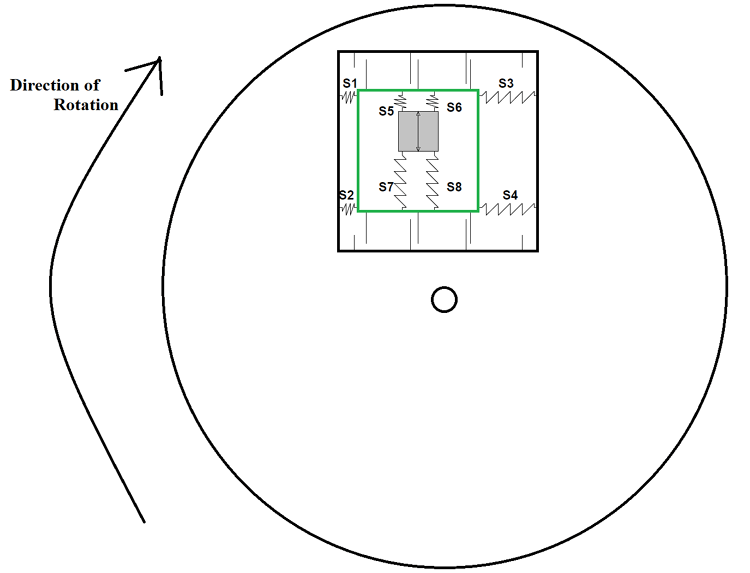
When the setup is installed on a rotating disk as shown, then mass resonating inside the setup will experience a force causing the displacement in the inner setup. You can see all the four springs S1 to S4 being deformed because of this displacement. This force experienced by resonating mass when suddenly placed on a rotating disk can be explained by the Coriolis Effect. Here is a small animation to illustrate how a MEMS gyroscope will work, we can notice how the force is exerted on the centerpiece (green color) based on the movement in the plate from X, Y and Z-axis.
If we skip the complex details, then it can be concluded that because of the sudden change in direction, there is displacement present in the inner layer. This displacement also causes the distance between capacitor plates on both the bottom and top layers to change. As explained in previous examples change in distance causes the capacitance to change. We can use this parameter to measure the rotational speed of the disk on which the device is placed.
MEMS Inertial Sensors
The MEMS Inertial Sensors or IMUs ( Inertial Measurement Unit ) are a combination of both accelerometer and gyroscope in one package. The IMU uses the data from both of these sensors to detect linear displacement and angular motion, which then is used to calculate the inertia of an object. IMUs are widely used in object stabilization devices such as Gimbals, they are also widely used in the aviation industry. The MPU6050 is one of the most popular IMU and it can be found on a variety of everyday gadgets.
MEMS Pressure sensors

We all know that when pressure is applied on an object it will strain until it reaches a breaking point. This strain is directly proportional to applied pressure until a certain limit and this property is used to design a MEMS pressure sensor. In the below figure you can see the structural design of a MEMS pressure sensor.
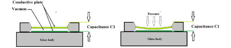
Here two conductor plates are mounted on a glass body and there will be a vacuum between them. One conductor plate is fixed and the other plate is flexible to move under pressure. Now if you take a capacitance meter and take a reading between two output terminals then you can observe a capacitance value between two parallel plates, this is because the entire setup acts as a parallel plate capacitor. Since it acts as a parallel plate capacitor then, as usual, all the properties of a typical capacitor apply to it now. Under the rest condition let’s call the capacitance between two plates to be C1.
Now if pressure is applied on the top layer it will deform and move closer to the bottom layer as shown in the figure. Because the layers get close, the capacitance between two layers gets increased. So higher the distances lower the capacitance and lower the distance higher the capacitance. If we connect this capacitance to an R-C resonator then we can get frequency signals representing the pressure. This signal can be given to a microcontroller for further processing and data processing.
MEMS Microphone

The design of the MEMS microphone is similar to the pressure sensor and the below figure shows the microphone's internal structure.

Let us consider the setup is at rest and in those conditions the capacitance between fixed plate and diaphragm is C1.
If there is noise in the environment then the sound enters the device through an inlet. This sound causes the diaphragm to vibrate making the distance between the diaphragm and fixed plate to change continuously. This, in turn, causes the capacitance C1 to change continuously. If we connect this changing capacitance to the corresponding processing chip we can get the electrical output for the changing capacitance. Because the changing capacitance directly relates to noise in the first place, this electrical signal can be used as a converted form of the input sound. The INMP441 and the ICS43434 are the most popular MEMS microphones among engineers. Both are digital microphones with I2S output.
MEMS Magnetometer

MEMS magnetometer is used for measuring the earth’s magnetic field. The device is constructed on the basis of Hall Effect or Magneto Resistive Effect. Most MEMS magnetometers use Hall Effect, so we will discuss how this method is used to measure the magnetic field strength. For that let us consider a conductive plate and have the ends of one side connected to a battery as shown in the figure.
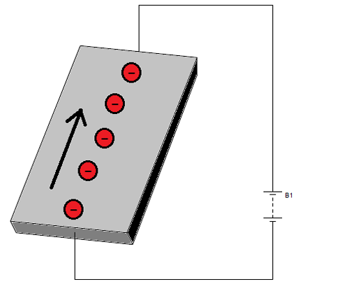
Here you can see the electrons flow direction, which is from the negative terminal to the positive terminal. Now if a magnet is brought near to the top of the conductor then electrons and protons in the conductor get distributed as shown in the below figure.
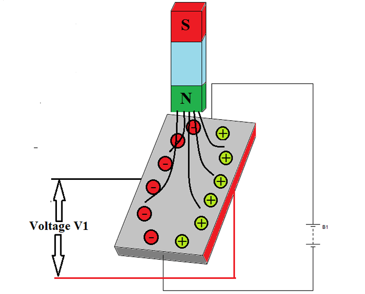
Here protons carrying positive charge get gathered at one side of the plane while electrons carrying negative charge get gathered at the exact opposite side. At this time if we take a voltmeter and connect at both ends then we will get a reading. This voltage reading V1 is proportional to the field strength experienced by the conductor on the top. The complete phenomenon of voltage generation by applying current and magnetic field is called the Hall Effect.
If a simple system is designed by using MEMS, based on the above model then we will get a transducer that senses field strength and provides linearly proportional electrical output.
MEMS Oscillator
While most of us are familiar with Quartz Crystal Oscillators, the MEMS oscillators are relatively new and modern. MEMS oscillators use the MEMS technology to create compact, cost-efficient timing devices. MEMS Oscillators are manufactured using silicon wafer processing and feature a resonator made of single-crystal silicon that vibrates at a specific frequency when voltage is applied. These vibrations generate a weak signal, which is amplified and processed through a phase-locked loop (PLL) as shown in the below block diagram of the MEMS oscillator
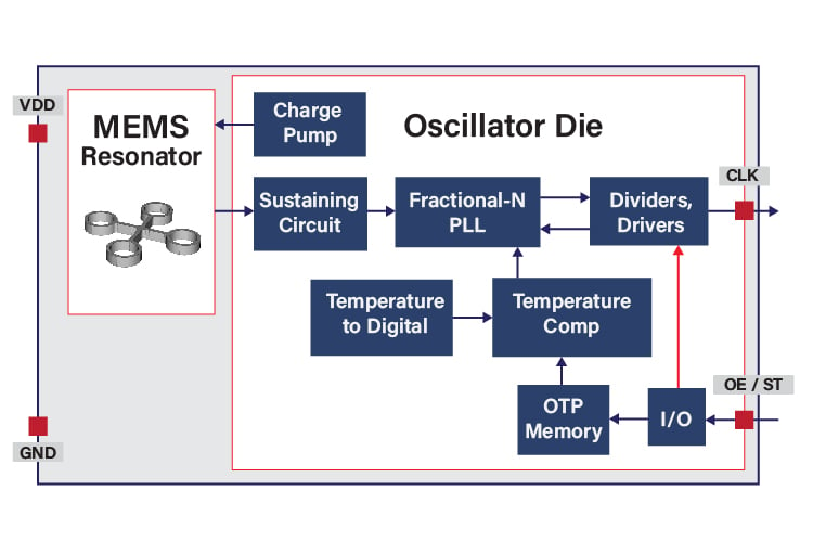
The oscillator includes temperature compensation to ensure stability across varying conditions and configurable output drivers for improved performance and noise reduction. A programmable architecture allows for flexible output frequencies and voltage settings, making MEMS oscillators suitable for a wide range of applications. With features like low jitter, vibration resistance, and reliable startup in harsh conditions, they are ideal for power-sensitive and space-constrained designs. Their key components include supply voltage (VDD), ground (GND), clock output (CLK), and an output enable/standby (OE/ST) pin to control the clock signal. You can also check out our MEMS vs Crystal Oscialltor article, if you want to know more about MEMS oscillators and how it differ from the normal crystal oscillators.
Many other MEMS devices are designed using MEMS technology and their number is also increasing every day. But all these devices carry a certain similarity in working and design, so by understanding the few examples mentioned above we can easily understand the working of other similar MEMS devices.
